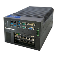
MX-E Series Hardware Guide Basler Cameras
55 Datalogic S.r.l.
Basler Cameras
The MX-E Series Processor and Impact Software can support a wide variety of Basler GigE cameras, in addition to the
models listed below, including all Ace and Scout models. Ace model numbers begin with “acA” and Scout model num-
bers begin with “scA.” For complete details and the most accurate specifications for these cameras, consult the manufac-
turer’s documentation.
Datalogic assumes no responsibility for the accuracy or timeliness of this third-party camera informa-
tion.
You must purchase a license from Datalogic to connect a third-party camera to the MX-E Series pro-
cessor.
Basler Aviator Cameras
Camera Connection
WARNING: THIRD-PARTY CAMERA REQUIREMENTS ARE DIFFERENT. THESE
CAMERAS REQUIRE +12 VDC POWER. USE CAUTION WHEN CONNECTING
POWER TO THESE CAMERAS.
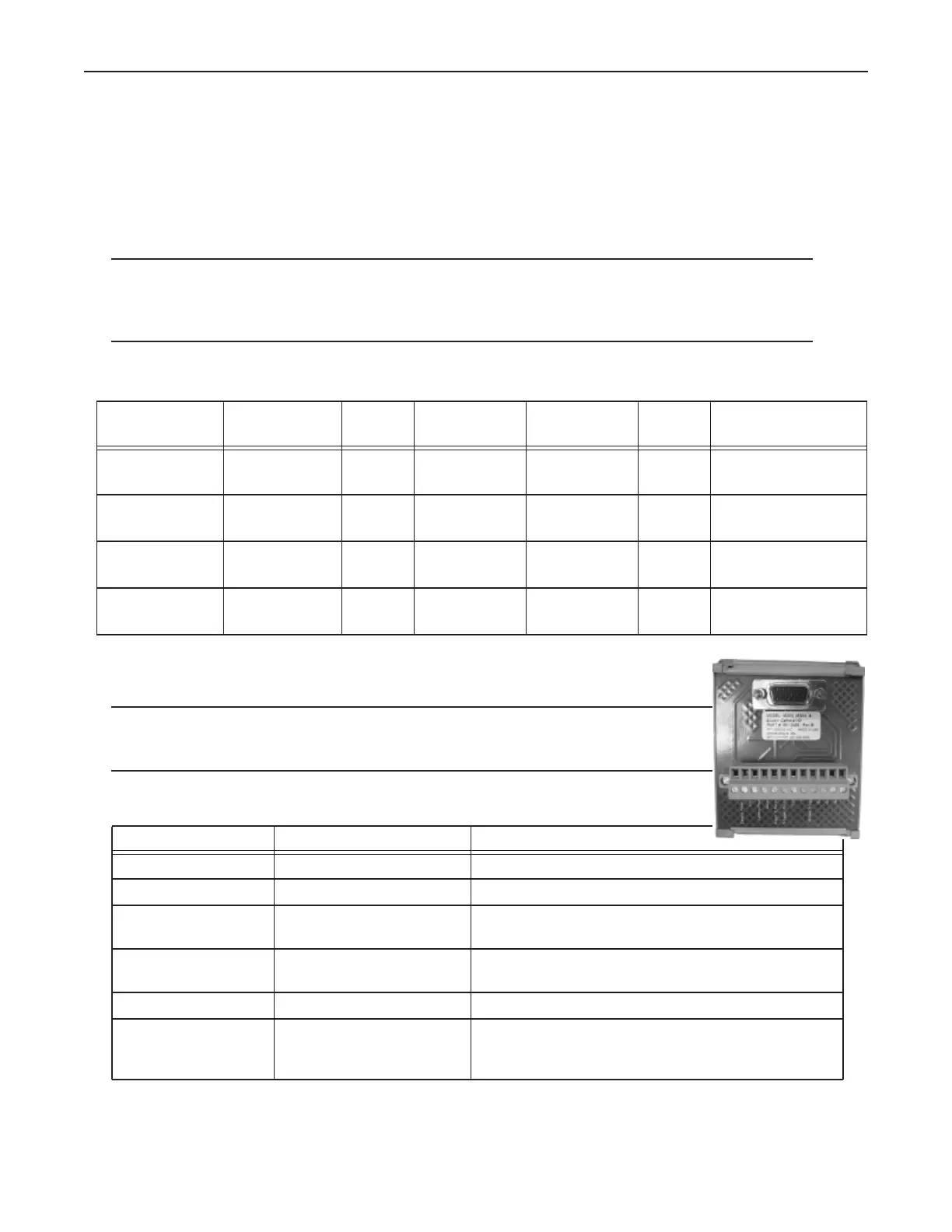
To connect power, trigger signals, and strobe outputs for these Basler camera models, use
cable 606-0673-xx (12-pin Hirose Male to HD-15) with terminal block 661-0400.
Model
(GigE)
Resolution
(Megapixels)
Color Image
Horizontal
Image Vertical FPS
(approx)
Minimum Software
Version Required
avA1000-100gm
avA1000-100gc
1No
Yes
1024 1024 101 10.3.0
avA1600-50gm
avA1600-50gc
1No
Yes
1600 1200 55 10.3.0
avA1900-50gm
avA1900-50gc
2No
Yes
1920 1080 51 10.3.0
avA2300-25gm
avA2300-25gc
3No
Yes
2239 1750 26 10.3.0
Terminal Signal Name Notes
Camera Power Ground Camera Ground
I/O Ground I/O Ground
Camera Power +VDC Camera Power +12 VDC recommended @ 500 mA Max
Maximum: +13.2 VDC
Output +VCC Power for Strobe Trigger Out +3.3 to +24 VDC; 50 mA Max
Maximum: +30 VDC
Input 2 Pullup +VCC DO NOT USE Not Currently Supported
Trigger Pullup +VCC Trigger In Pullup - use if
Trigger In needs sourcing
input
Recommended: +24 VDC