Smartek Cameras MX-E Series Hardware Guide
Datalogic S.r.l. 66
Smartek Cameras
Smartek Camera Connection
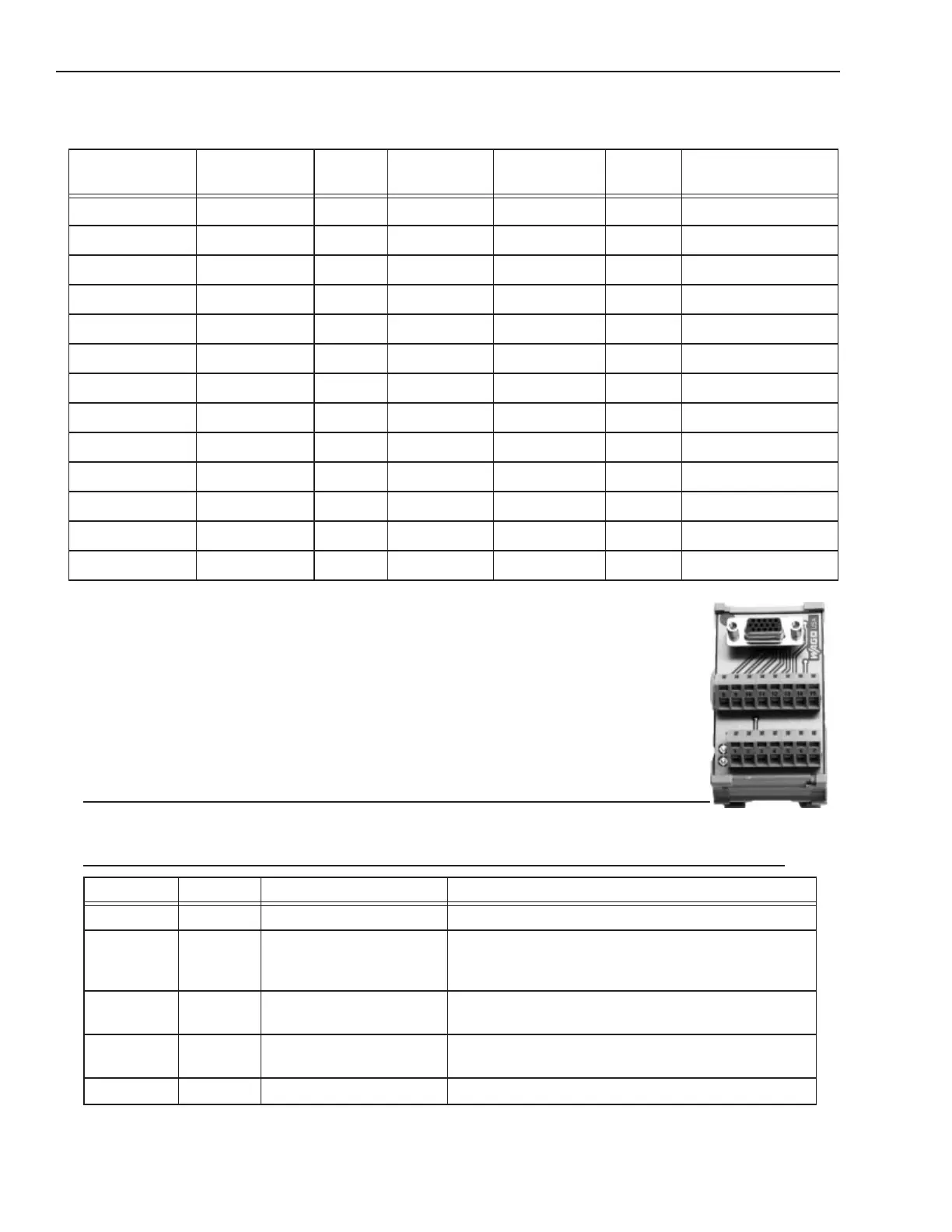
Camera power, trigger signal, and strobe trigger can be connected to the camera using one of two
methods: a terminal block with a cable or an unterminated cable. Use a terminal block (248-0136)
with the optional Hirose 12-pin to HD-15 camera cable (606-0673-xx). Without a terminal block,
use the optional Hirose 12-pin to unterminated cable (part number 606-0671-xx).
NOTE: Do NOT use terminal block 248-0141 to connect this camera. It will NOT provide the cor-
rect signal levels.
WARNING: THE POWER AND GROUND CONNECTIONS FOR THIS CAMERA ARE
DIFFERENT FROM OUR CAMERAS AND OTHER THIRD-PARTY CAMERAS. USE CAUTION WHEN CON-
NECTING POWER TO THESE CAMERAS.
Model
(GigE)
Resolution Color Image
Horizontal
Image Vertical FPS
(Approx)
Minimum Software
Version Required
GC651M .3 No 659 494 120 11.2.0
GC652M .3 No 659 494 90 11.2.0
GC653M .3 No 659 494 90 11.2.0
GC781M .5 No 782 682 64 11.2.0
GC1021M 1 No 1024 1024 60 11.2.1
GC1031M .8 No 1034 770 30 11.2.0
GC1291M 1.2 No 1296 966 30 11.2.0
GC1391M 1.4 No 1392 1040 20 11.2.0
GC1392M 1.4 No 1392 1040 30 11.2.0
GC1601M 1.9 No 1600 1200 30 11.2.1
GC1621M 2 No 1628 1236 25 11.2.0
GC1921M 2 No 1920 1080 32 11.2.1
GC2441M 5 No 2448 2050 15 11.2.0
Terminal Color Signal Name Notes
1 Wht/Blu Camera Power Ground
2 Wht/Org Camera Power VCC +12 VDC @ 300 mA Max (3.6 W)
Minimum: +10 VDC
Maximum: +24 VDC
3 Wht/Brn Strobe Trigger - 270 Ohm 2W resistor between Wht/Brn wire and Strobe
Power Ground
4 Brn/Wht Strobe Trigger + +5 to +24 VDC
Maximum: +24 VDC
5 Wht/Grn DO NOT USE