EasyManuals Logo

Datalogic MX-E Series User Manual

Datalogic MX-E Series
120 pages
To Next Page IconTo Next Page
To Previous Page IconTo Previous Page
Page #73 background imageLoading...
Page #73 background image
MX-E Series Hardware Guide Smartek Cameras
67 Datalogic S.r.l.
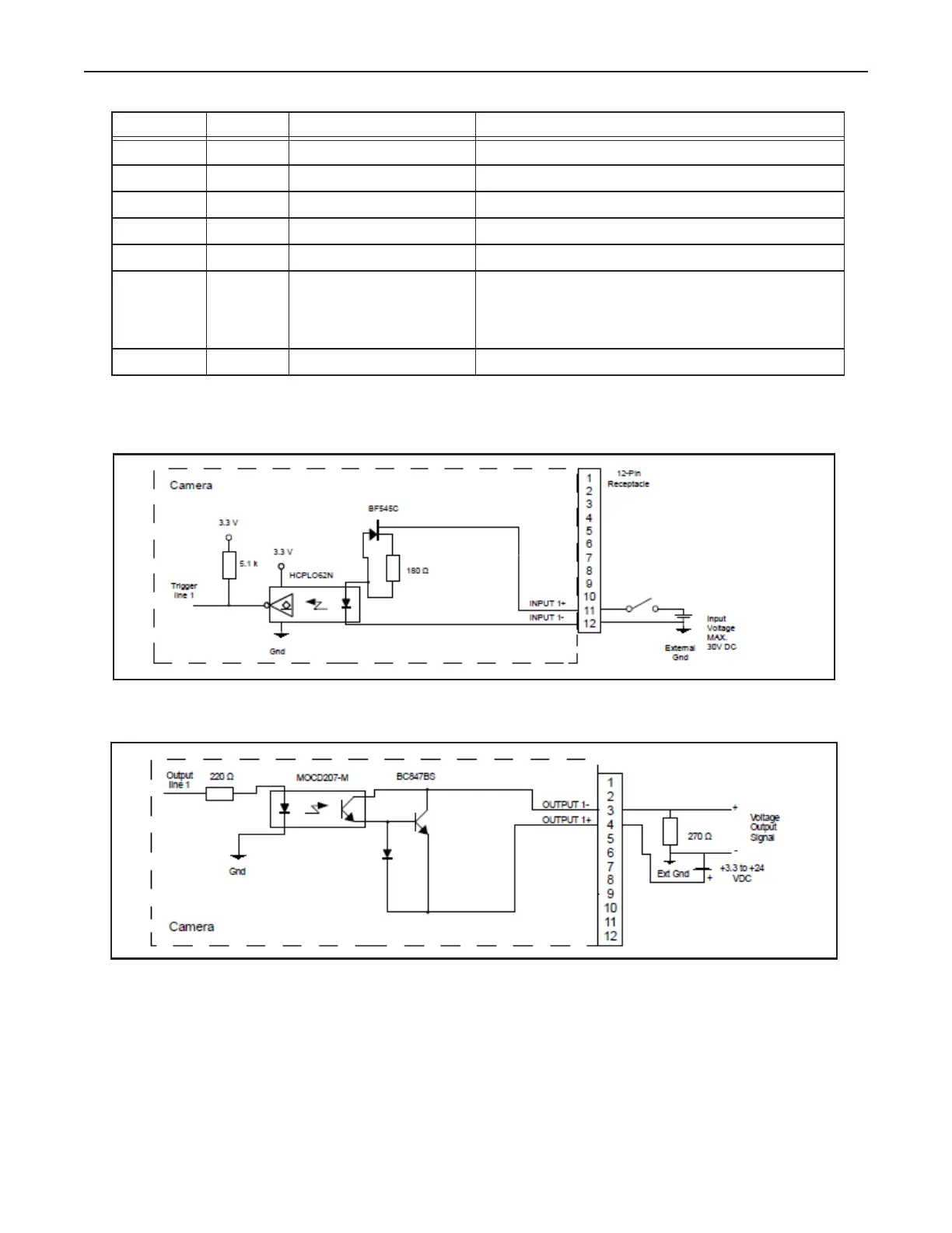
Smartek Camera Circuit Diagrams
Smartek Camera Trigger Input Circuit
Smartek Camera Strobe Output Circuit
6 Wht/Gry DO NOT USE
7 Gry/Wht DO NOT USE
8 Blu/Wht DO NOT USE
9 Org/Wht DO NOT USE
10 Grn/Wht DO NOT USE
11 Red/Blu Camera Trigger + +0 to +24 VDC
Off: 0 to + 1.4 VDC
On: +2.2 to + 24 VDC
Maximum: +24 VDC
12 Blu/Red Camera Trigger -
Terminal Color Signal Name Notes

Table of Contents

Questions and Answers:

Question and Answer IconNeed help?

Do you have a question about the Datalogic MX-E Series and is the answer not in the manual?

Datalogic MX-E Series Specifications

General IconGeneral
BrandDatalogic
ModelMX-E Series
CategoryMachine Vision Systems
LanguageEnglish

Related product manuals