Processor Outputs MX-E Series Hardware Guide
Datalogic S.r.l. 104
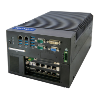
Processor Outputs
The MX-E Series Processors contain sixteen general-purpose output connections.
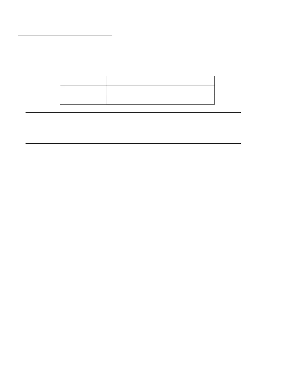
The table below describes the output’s electrical characteristics.
Note: An external power source is required to power an output load. The outputs are merely switches that are open or
closed. All output connections must use properly grounded and shielded cable.
Note: The Trigger Signal and Strobe Output for M-Series and E-Series cameras are separate and not part of the MX-E
Series Processor inputs and outputs. See “M-Series and E-Series Cameras” on page 23 for details.
Supply Voltage +12 to +24 VDC (±10%)
Maximum Output +35 VDC
Output Current 100 Milliamperes per channel (maximum)