107 Datalogic S.r.l.
CHAPTER 5
Cable Reference
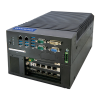
This chapter documents MX-E Series Processor and Camera cable assemblies.
Processor Cables
The following cables connect different hardware devices to the Processor.
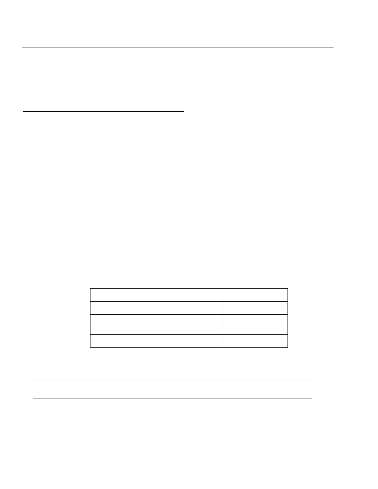
Ethernet
An Ethernet cable (Part number 606-0677-xx) is used to connect the MX-E Series Processor to the GigE camera and
between the Processor and any external network. The last two digits of the part number indicate the cable length in feet.
We recommend you use shielded Cat5e Ethernet cable or better to connect the camera and the Processor. Cat6 cable is
required for distances greater than 25 meters. Using any other cable may cause intermittent data transmission.
A crossover cable is not required because the Ethernet ports are auto-negotiating; that is they can tell the difference
between a peer-to-peer connection and a router/switch connection and they configure themselves and the communications
to suit the environment.
Input/Output
The terminal block and cable for connecting MX-E Series processor are listed in the table below. For connection dia-
grams, see “Processor I/O Connection” on page 99. The last two digits of the part number indicate the cable length in
meters.
Power Supply
This equipment is to be powered by a Listed power supply for the U.S. and Canada, or a power supply that meets the
requirements for use where either IEC 60950 or EN60950 is applicable.
See “Power Supply Connection” on page 17 for more details on wiring the power supply cable.
Connector Type Part Number
Terminal Block - 37 pin D-sub to Screw Terminal 248-0110
I/O Cable - 37 pin D-sub Male to Male Cable (for
use with above terminal block)
606-0675-xx
37 pin D-sub Male to pigtail (remove one end) 606-0675-xx