MX-E Series Hardware Guide JAI Cameras
47 Datalogic S.r.l.
JAI Cameras
NOTE: See “JAI Camera I/O Signals” on page 54 for important information about camera and strobe signals.
*See “Color shading support” on page 53 for special camera configuration settings.
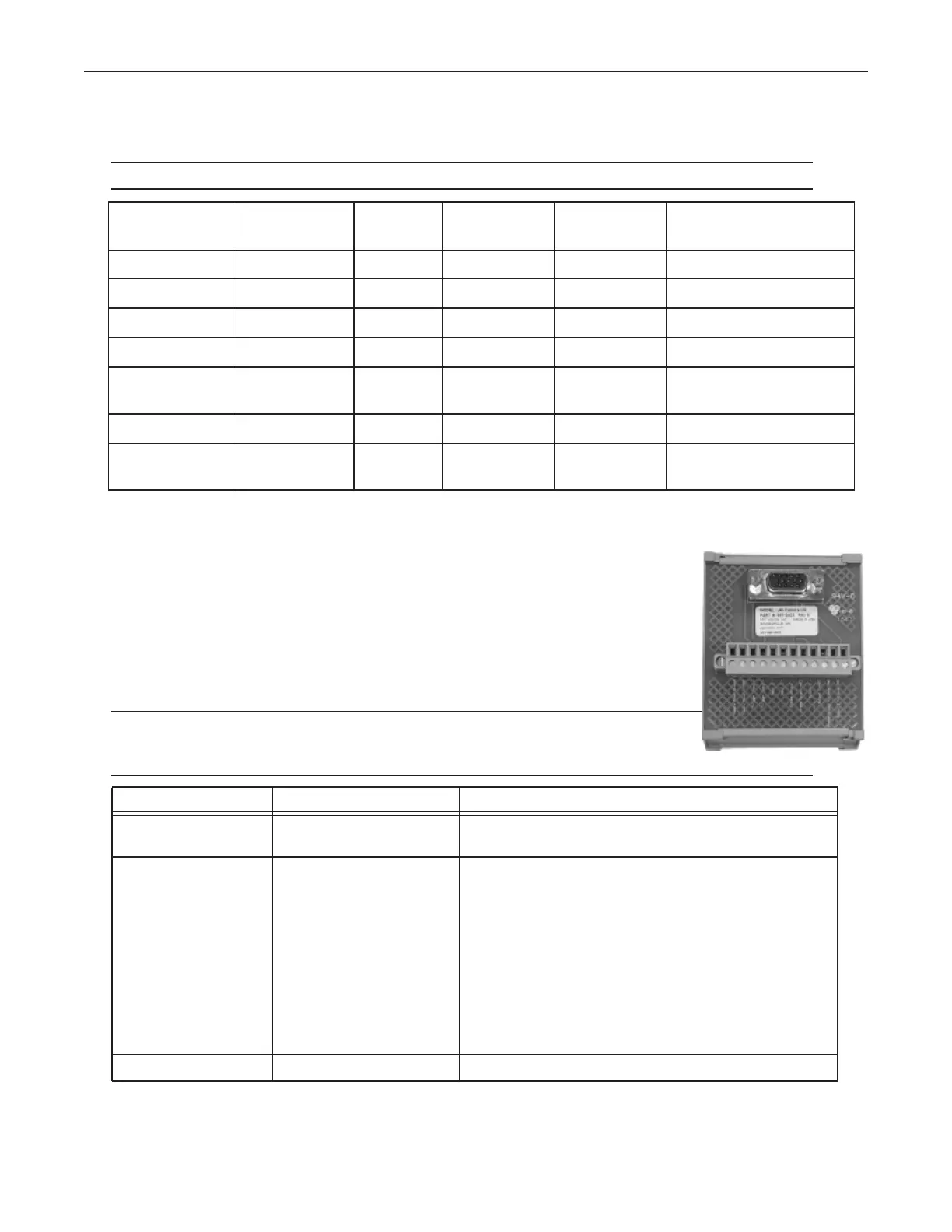
JAI Camera Connection
To connect JAI camera power, trigger signals, and strobe outputs, use cable 606-0673-xx
(12-pin to HD-15) with terminal block 661-0402.
NOTE: Do NOT use terminal block 248-0141 to connect this camera. It will NOT provide
the correct signal levels.
WARNING: THE POWER AND GROUND CONNECTIONS FOR THIS CAMERA
ARE DIFFERENT FROM OUR CAMERAS AND OTHER THIRD-PARTY CAM-
ERAS. USE CAUTION WHEN CONNECTING POWER TO THESE CAMERAS.
Model
(GigE)
Resolution
(Megapixels)
Color Image
Horizontal
Image Vertical Minimum Software Ver-
sion Required
AT-200GE* 2 Yes 1624 1236 10.3.0
AM-800GE 8 No 3296 2472 10.3.0
AM-1600-GE 16 No 4872 3248 10.6.0
CM-140GE 1.4 No 1392 1040 11.0.0
AT-140GE* 1.4 Yes
(3 CCD)
1392 1040 10.5.0
CM-140GE-UV 1.4 Ultraviolet 1392 1040 10.2.0
CM-030GE-RH
(remote head)
0.3 No 659 494 10.2.0
Terminal Signal Name Notes
Camera Power
Ground
Camera Ground
Camera Power
+12VDC
Camera Power CM-140GE-UV and CM-030-GE-RH
+12 VDC @ 350 mA Max (4.1 W)
Maximum: +13.2 VDC
AM-800GE
+12VDC to +24VDC ±10%, 8.16W (at normal, Full resolu-
tion, DC+12V)
AT-200GE
+10.8VDC to +26.4VDC, 0.67 A (Typical, Full frame, DC
+12V in)
AM-1600GE
+12.0VDC ±10%, 7.5W (Typical, Continuous Mode)
Trigger Input - Camera Trigger -