JAI Cameras MX-E Series Hardware Guide
Datalogic S.r.l. 48
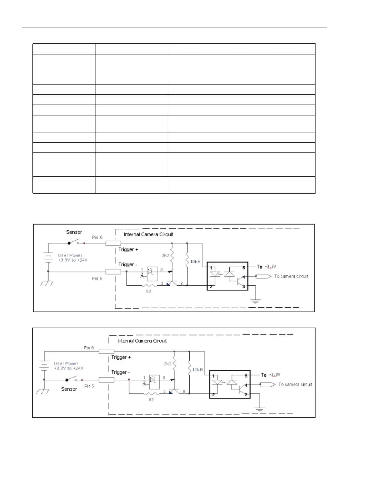
JAI Camera Circuit Diagrams
JAI Camera Trigger Input Circuit (sourcing)
JAI Camera Trigger Input Circuit (sinking)
Trigger Input + Camera Trigger + +0 to +24 VDC
Off: 0 to +2.0 VDC
On: +4.0 to + 24 VDC
Maximum: +24 VDC
Input 2 - Not Currently Supported DO NOT USE
Input 2 + Not Currently Supported DO NOT USE
Strobe Output - Strobe Output Ground
Strobe Output +VCC Power for Strobe Output +5 to +24 VDC
Maximum: +24 VDC; 100 mA
Output 2 - Not Currently Supported DO NOT USE
Output 2 +VCC Not Currently Supported DO NOT USE
Strobe Output
Pull down GND
Strobe Output Pull down -
use if Strobe Output needs
sourcing output
Output 2 Pull down
GND
Not Currently Supported DO NOT USE
Terminal Signal Name Notes