Basler Line Scan Camera MX-E Series Hardware Guide
Datalogic S.r.l. 60
Basler Line Scan Camera
Basler Line Scan Camera Connection
This section includes information for the Basler color line scan camera model ruL2098-10gc
and monochrome model raL8192-12gm.
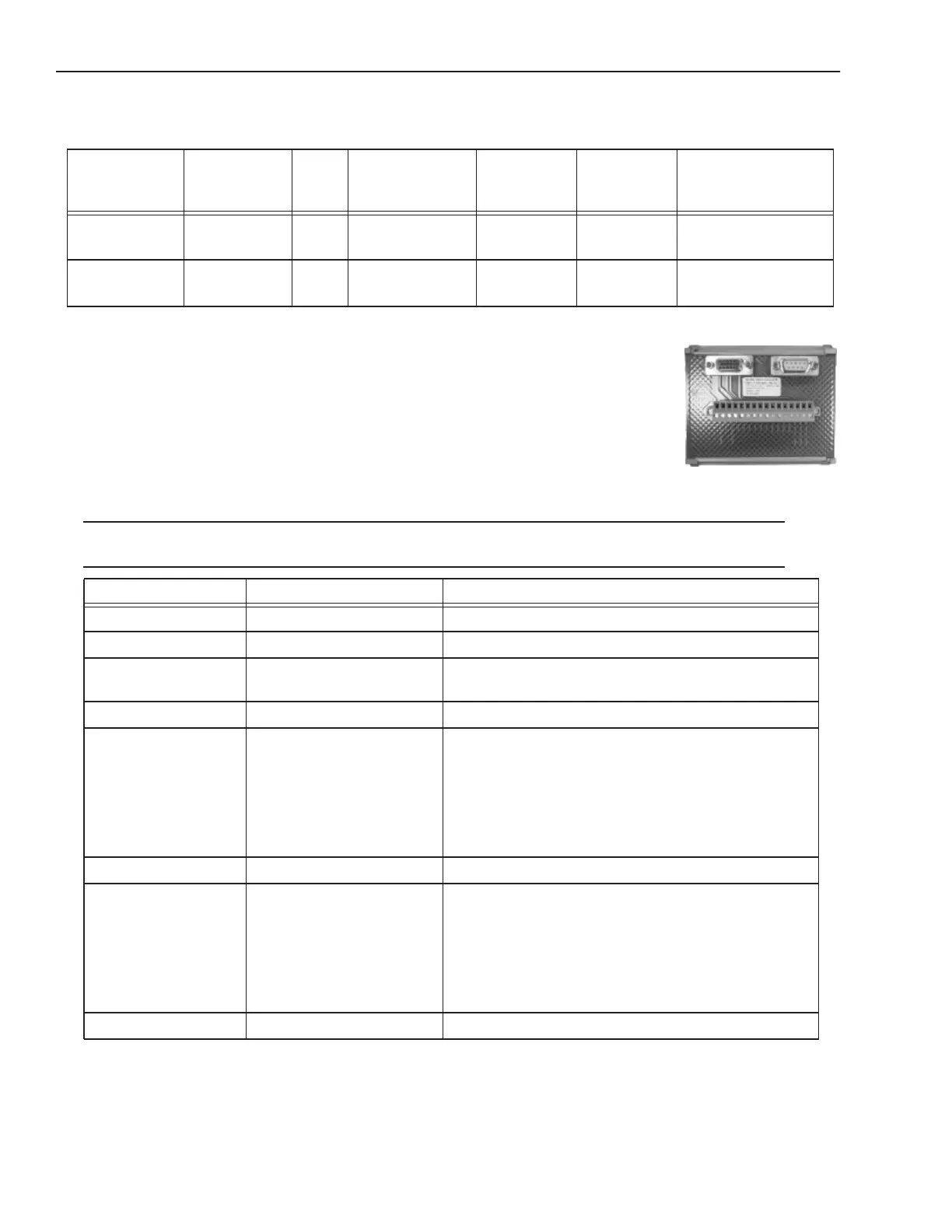
To connect the camera, use terminal block 661-0401 with cable 606-0673-xx (12-pin to HD-
15 camera I/O) and cable 606-0674-xx (6 pin to DB9 camera power). For details about pro-
gramming the Line Trigger, refer to the Impact Reference Guide (843-0093)
NOTE: Do NOT use the M2xx/M3xx terminal block (661-0400) or M1xx block (661-0399) to connect this camera. They
will NOT provide the correct signal levels.
Model
(GigE)
Sensor Size Color Maximum Line
Rate
Pixel Size Maximum
Frame
Height
Minimum Software
Version Required
ruL2098-10gc 2098 pixels
x 3 lines
Yes 9.2 kHz 14 x 14 μm 1988 pixels 11.5.0
raL8192-12gm 8192 pixels
x 1 line
No 12 kHZ 3.5 x 3.5 μm 12288 pixels 11.7.0
Terminal Signal Name Notes
Camera Power Ground Camera Ground See Note 1 Below
I/O Ground I/O Ground See Note 1 Below
Camera Power
+12VDC
Camera Power +12 VDC (+-10%) @ 500 mA Max
Input 1 - No Connection DO NOT USE
Input 1 + Frame Start Trigger As sinking input
Off 0 to +0.8 VDC
On: +2.0 to +5 VDC
As sourcing input (see Input 1 Pullup)
Off: +2.0 to +5 VDC
On 0 to +0.8 VDC
Maximum: +5 VDC
Input 2 - No Connection DO NOT USE
Input 2 + Single Line Trigger
OR
Phase A Line Trigger
(Quadrature Encoder)
As sinking input
Off 0 to +0.8 VDC
On: +2.0 to +5 VDC
As sourcing input (see Input 2 Pullup)
Off: +2.0 to +5 VDC
On 0 to +0.8 VDC
Maximum: +5 VDC
Input 3 - No Connection DO NOT USE