99 Datalogic S.r.l.
CHAPTER 4
Processor I/O
There are two versions of the MX-E processor, one with sourcing outputs - the model number contains a “P” (for example
MX-E20-2-P-1) and one with sinking outputs - the model number contains an “N” (for example MX-E20-2-N-1)
This section discusses the MX-E Series Processor I/O scheme. Refer to this
section for all specifications when wiring your inputs and outputs into the
Processor.
Note: Your MX-E Series Processor does not provide a voltage source for
inputs and outputs – it must be provided by an external source. Refer to the
module tables below for more voltage requirement information.
Note: The Trigger Signal and Strobe Output for M-Series cameras are sepa-
rate and not part of the MX-E Series Processor inputs and outputs. See “M-
Series and E-Series Cameras” on page 23 for details.
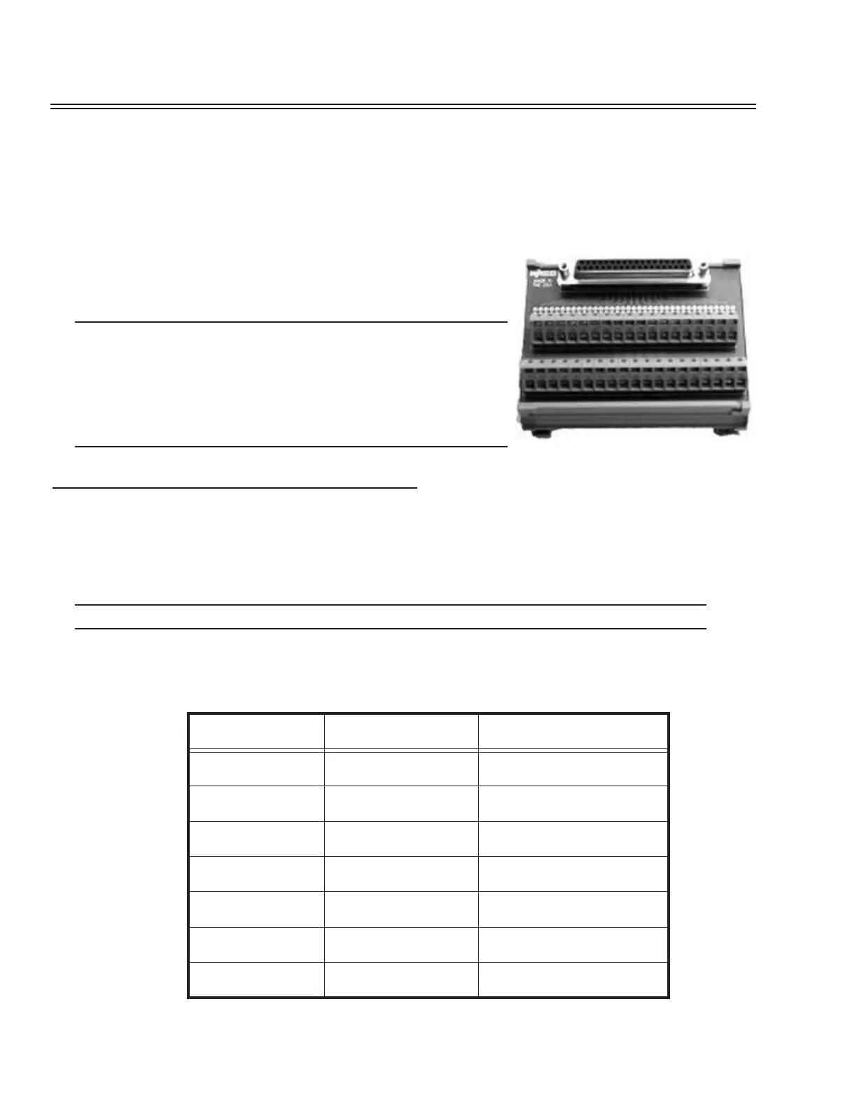
Processor I/O Connection
To connect MX-E Series processor input and output signals use either cable 606-0675-xx (37 pin D-sub Male to Male
Cable) with terminal block 248-0110 or remove one end (to create pigtail) with no terminal block. Use shielded cable for
all connections.
IMPORTANT: Do not connect or disconnect the cable while power is on.
Current Sinking (NPN) I/O
Connector and terminal numbers for model numbers containing the letter “N” are listed in the following table.
Connector or terminal
number
Color Code Signal Name
1
2
Black
Brown
Output Minus (Note 1)
Input 1- and Event 1-
3
4
Red
Orange
Input 2- and Event 2-
Input 3-
5
6
Yellow
Green
Input 4-
Input 5-
7
8
Blue
Purple
Input 6-
Input 7-
9
10
Gray
White
Input 8-
Input 9-
11
12
Pink
Light Green
Input 10-
Input 11-
13
14
Black/White
Brown/White
Input 12-
Input 13-