Processor I/O Connection MX-E Series Hardware Guide
Datalogic S.r.l. 100
NPN NOTES:
1. Common Minus for output ports (External 12 to 24VDC Minus)
2. Common Plus for input ports (External 12 to 24VDC Plus)
3. Common Plus for output ports (Not an output voltage source. External 12 to 24VDC Plus is required)
Current Sourcing (PNP) I/O
Connector and terminal numbers for model numbers containing the letter “P” are listed in the following table.
15
16
Red/White
Orange/White
Input 14-
Input 15-
17
18
Green/White
Blue/White
Input 16-
Input Plus (Note 2)
19 Purple/White No Connection
20
21
Red/Black
Orange/Black
Output Minus (Note 1)
Output 1
22
23
Yellow/Black
Green/Black
Output 2
Output 3
24
25
Gray/Black
Pink/Black
Output 4
Output 5
26
27
Pink/Red
Pink/Blue
Output 6
Output 7
28
29
Pink/Green
Light Blue
Output 8
Output 9
30
31
Light Blue/Black
Light Blue/Red
Output 10
Output 11
32
33
Light Blue/Blue
Light Blue/Green
Output 12
Output 13
34
35
Gray/Red
Gray/Green
Output 14
Output 15
36
37
Purple/Black
Blue/Black
Output 16
Output Plus (Note 3)
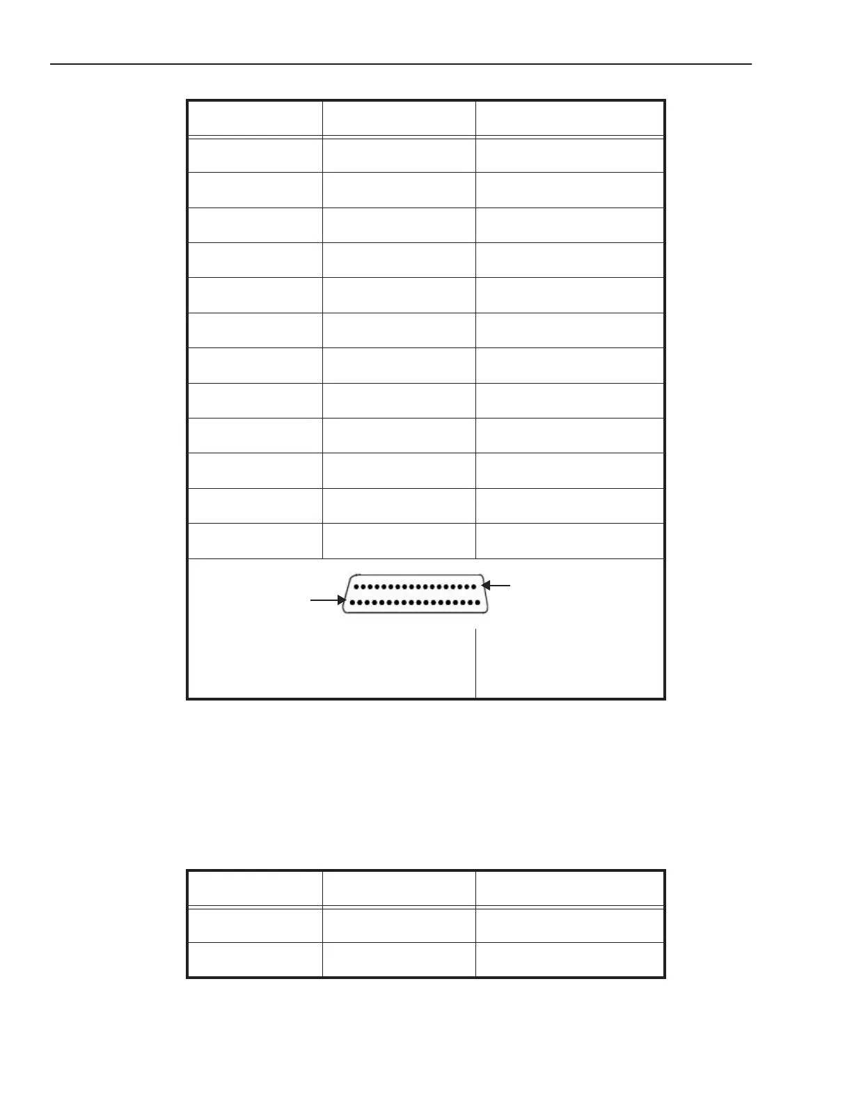
J1 (37 Pin "D" Sub Female)
AMP Part 747916-4
Part 244-0287
(Solder Side)
Connector or terminal
number
Color Code Signal Name
1
2
Black
Brown
Input Minus (Note 4)
Input 1- and Event 1-
3
4
Red
Orange
Input 2- and Event 2-
Input 3-
Connector or terminal
number
Color Code Signal Name
Pin 1
Pin 37