Processor Inputs MX-E Series Hardware Guide
Datalogic S.r.l. 102
Processor Inputs
The MX-E Series Processors contain sixteen general-purpose input connections.
Two inputs serve as both event and polled inputs (Inputs 1 and 2). The remaining inputs are polled. The event inputs are
interrupt-driven which means that a change of state on the input will immediately cause an action and any inspection task
that uses that input will be queued to run. Polled input means that the input’s status is checked based on conditions defined
in the inspection task.
Interrupt-driven inputs are edge-triggered and the duration of the input pulse must be longer than the debounce time. The
active trigger edge (rising, falling, or both), input pulse duration, and debounce, are all configured in the Vision Program
Manager Settings tab.
This table describes the input characteristics.
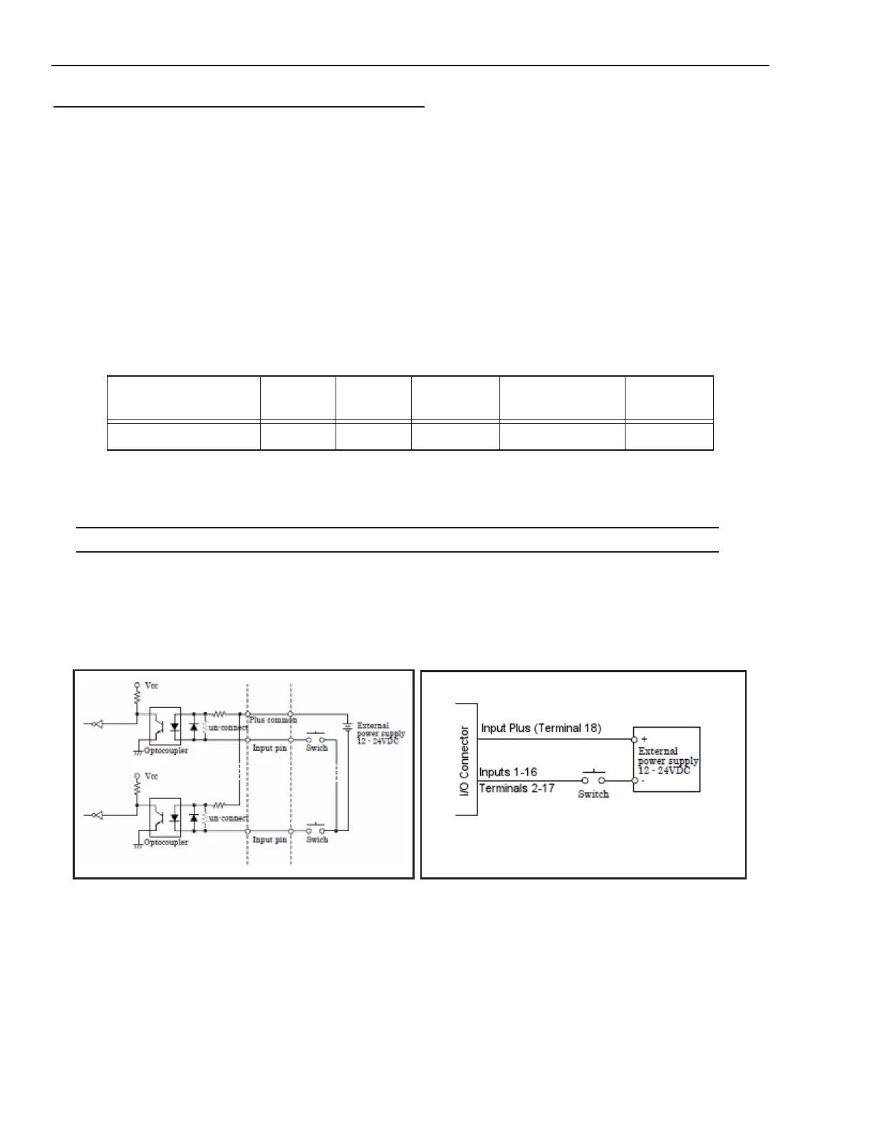
Input Wiring
Note: All connections to inputs must be made using properly grounded shielded cable.
Current Sinking (NPN) Input Circuit
The diagram below shows how to wire a sensor to a general purpose or event input for model numbers containing the let-
ter “N.” All inputs are compatible with current sinking output signals. Pin 18 is the “Input Plus Common” connection for
all the inputs.
Input Resistance
(nominal)
Input
Voltage
Turn On
Current
Turn Off
Current
Maximum
Current
Isolated
Voltage
4.7k @ 5-24 Vdc >2 mA < 0.16Ma 5.1 mA @ 24Vdc 1000 Vrms