MX-E Series Hardware Guide Top Panel Connections
7 Datalogic S.r.l..
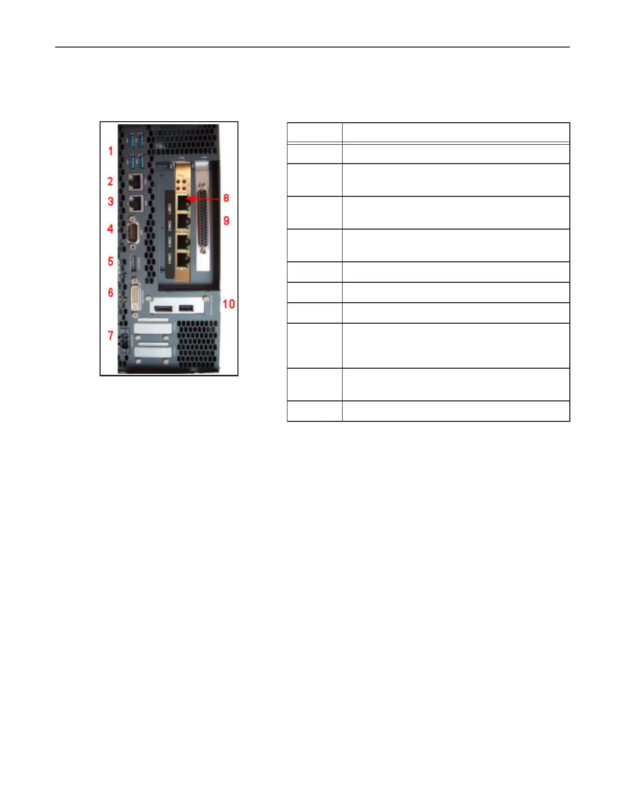
Top Panel Connections
This illustration shows the connections on the Processor’s top panel.
Symbol Function
1 USB 3.0 (x 4)
2 ETH2 - Ethernet 2 (See “Status Lights” on
page 10)
3 ETH1 - Ethernet 1 (See “Status Lights” on
page 10)
4 RS232 Serial Port (COM 1) - See “Serial Port”
on page 108
5 Display Port connection
6 Monitor/Panel connection for smart monitor
7 Supply Voltage
8 Camera Connectors Cam1 through Cam4
Cable 606-0677-xx (Also see “Status Lights” on
page 10)
9 37-pin D-Sub Digital I/O (See “Processor I/O
Connection” on page 99)
10 (optional) USB 2.0 and Display Port