Output Wiring MX-E Series Hardware Guide
Datalogic S.r.l. 106
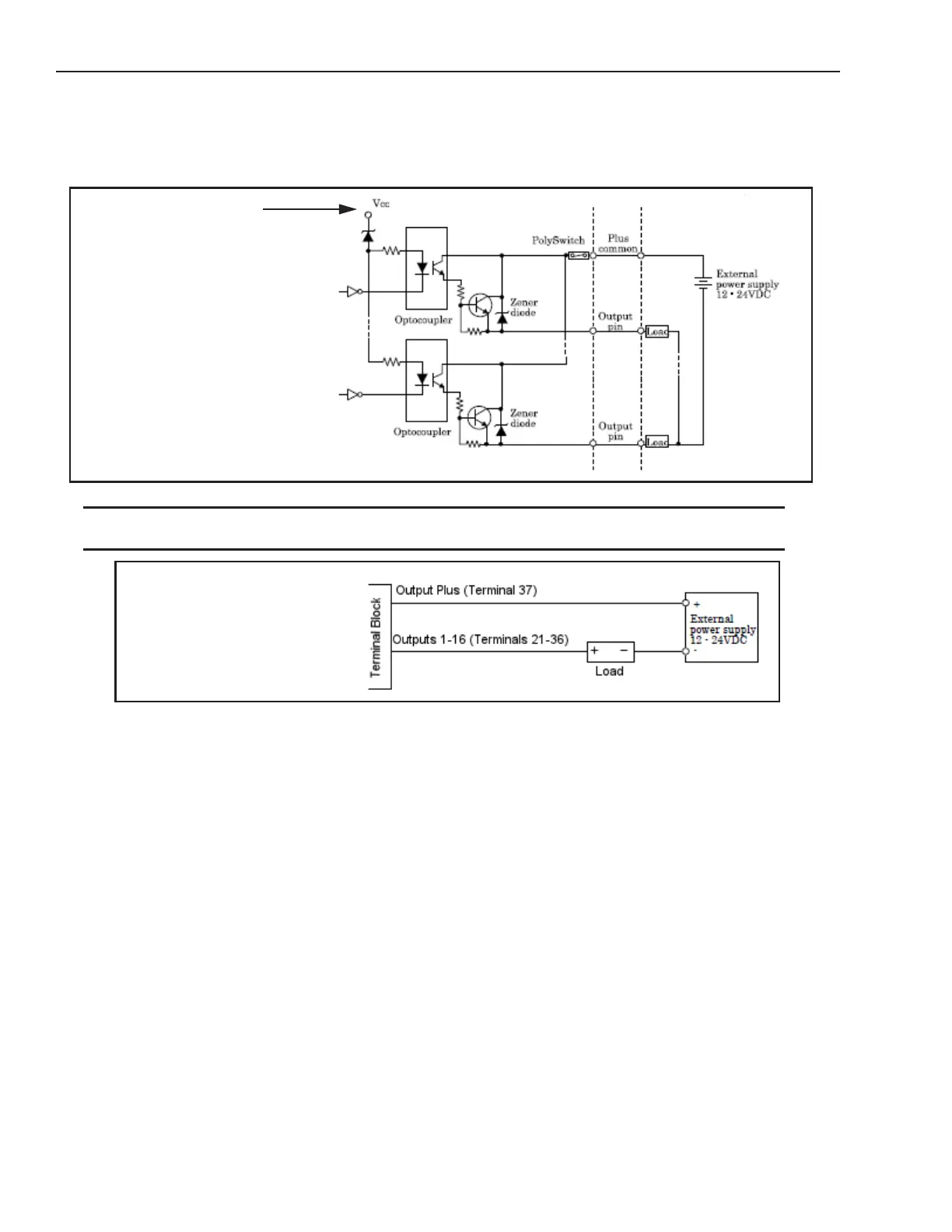
Current Sourcing (PNP) Output Circuit
The diagrams below show internal circuit diagrams and how to wire processor outputs for model numbers containing the
letter “P.”
NOTES: To prevent output damage, all inductive loads must have noise suppressors connected directly across the load, as
close to the load as possible.
This is an internal connection, not
an output voltage source. An exter-
nal power source must be con-
nected to the Load, as indicated.
Output Plus is not an output volt-
age source. An external power
source must be connected, as
indicated.