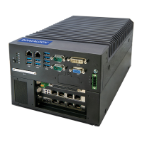
MX-E Series Hardware Guide SVS-Vistek Cameras (non-IP67 rated)
71 Datalogic S.r.l.
SVS-Vistek (non-IP67) Camera Connection
This camera uses two cables, one for Ethernet and one for power and trigger signals. For the Ether-
net connection, use cable 606-0677-xx. To connect power and trigger signals, use a terminal block
(248-0136) with the optional Hirose 12-pin to HD-15 camera cable (606-0673-xx).
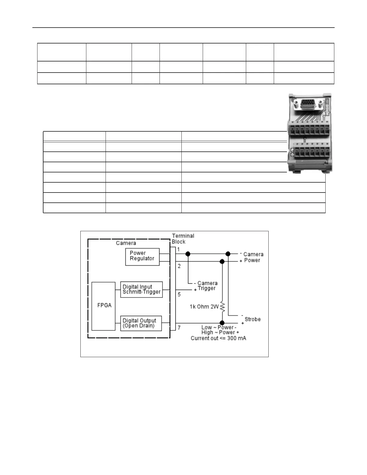
SVS-Vistek Non-IP67 I/O Circuit
eco655MVGE
eco655CVGE
5No
Yes
2456 2048 10 10.4.0
10.5.0
eco814MT 9 No 3360 2712 7 11.2.1
eco694MT 6 No 2752 2204 10 11.2.1
Terminal Signal Name Notes
1 (Wht/Blu) Camera Ground
2 (Wht/Org) Camera Power Min +10 VDC to Max +25 VDC
3 & 4 DO NOT USE Not Currently Supported
5 (Wht/Grn) Camera Trigger In 0 to +24 VDC
6 DO NOT USE Not Currently Supported
7(Gry/Wht) Trigger Out to Strobe 0 to +24 VDC; 300 mA Max
8, 9, 10, 11, 12 DO NOT USE Not Currently Supported