Appendix S – RFID Overview
Class Series 2 Programmer’s Manual 299
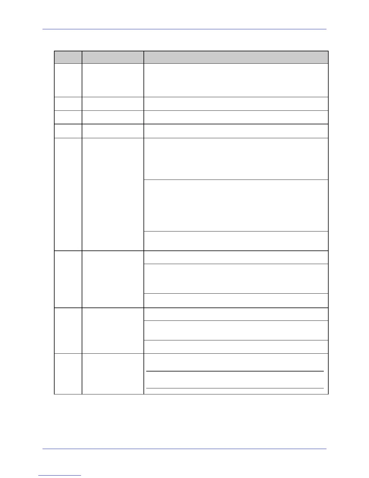
Field Valid Inputs Meaning
a
1, 2, and 3
Operation to perform, where:
1 = Read (report to host)
2 = Write
3 = Write w/ Read back and Verify
bbb
Wnx RFID Hexadecimal Operation, where no “n” is an implied 1.
c
0 Not Used, should be 0
d
0 Not Used, should be 0
HF: Lock after write, where:
x = 0 – Use printer setup to determine if lock is performed.
x = 1 – Lock after write.
yy = Not Used
UHF EPC Gen2: Lock after write, where:
x = 0 – Use printer setup to determine if lock is performed.
x = 1 – Lock after write.
yy = Lock state where “01”is permalock, “10” is pwd-write
lock or “11” is both states
eee
xyy
UHF other tag types: Not Used, should be 000
HF: Starting block number to write.
UHF EPC Gen2: Block address where “0001” is EPC data, “0002”
is Tag ID or “0003” is user memory. Using “0000” is for EPC
data also (for backwards compatibility).
ffff
0000 – 9998
UHF other tag types: Not Used, should be 0000
HF: Not Used, should be 0000
UHF EPC Gen2: Data word offset – currently only used for read
operation
gggg
0000
UHF other tag types: Not Used, should be 0000
jj…j
Valid hexadecimal
pairs per character
followed by a
termination
character.
Data to write to the tag.
UHF data length must be 16 or 24 for EPC, 16 for Tag ID or
multiples of four for user memory sections.
 Loading...