Installing System Components | 277
4 Disconnect all the cables from the backplane. See Figure 3-90 for 3.5-
inch hard drives and Figure 3-91 for 2.5-inch hard drives.
Note the routing of the cable on the chassis as you remove them from
the system. You must route these cables properly when you replace
them to prevent the cables from being pinched or crimped.
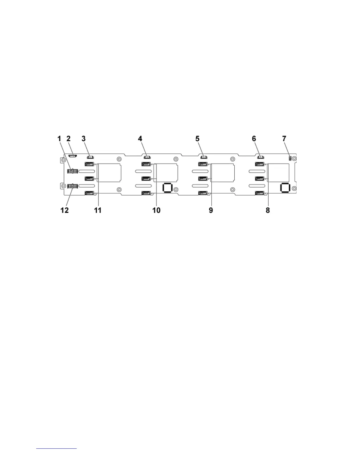
Figure 3-90. Back View of the 3.5” Direct Backplane
backplane power connector for
power supply 1
1x8pin fan controller board
connector
SGPIO connector 4 for system board
SGPIO connector 3 for system
SGPIO connector 2 for system board
2
SGPIO connector 1 for system
board 1
SATA2 hard drive connectors 1, 2
and 3 for system board 1 (from top
SATA2 hard drive connectors 1, 2
and 3 for system board 2 (from top to
SATA2 hard drive connectors 1, 2
and 3 for system board 3 (from top
SATA2 hard drive connectors 1, 2
and 3 for system board 4 (from top to
backplane power connector for

 Loading...