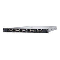
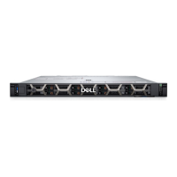
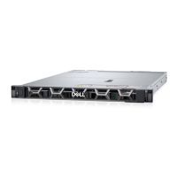
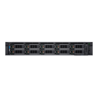
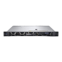
Figure 46. Configuration 17: No BP (0 configuration)
NOTE:
Follow the sequential order as shown in the table to remove the cables, to install the cables follow the reverse
sequential order.
Table 88. No BP (0 configuration)
Order From To
1 LFT_CP (left control panel connector) Ear to handle (left control panel connector)
2 RGT_CP (right control panel connector) Ear to handle (right control panel connector)
3 J_INTRUSION_DET1 (intrusion switch connector)
4 J_FRONT_VIDEO (front video connector) VGA (video connector)
Installing and removing system components 91

 Loading...
