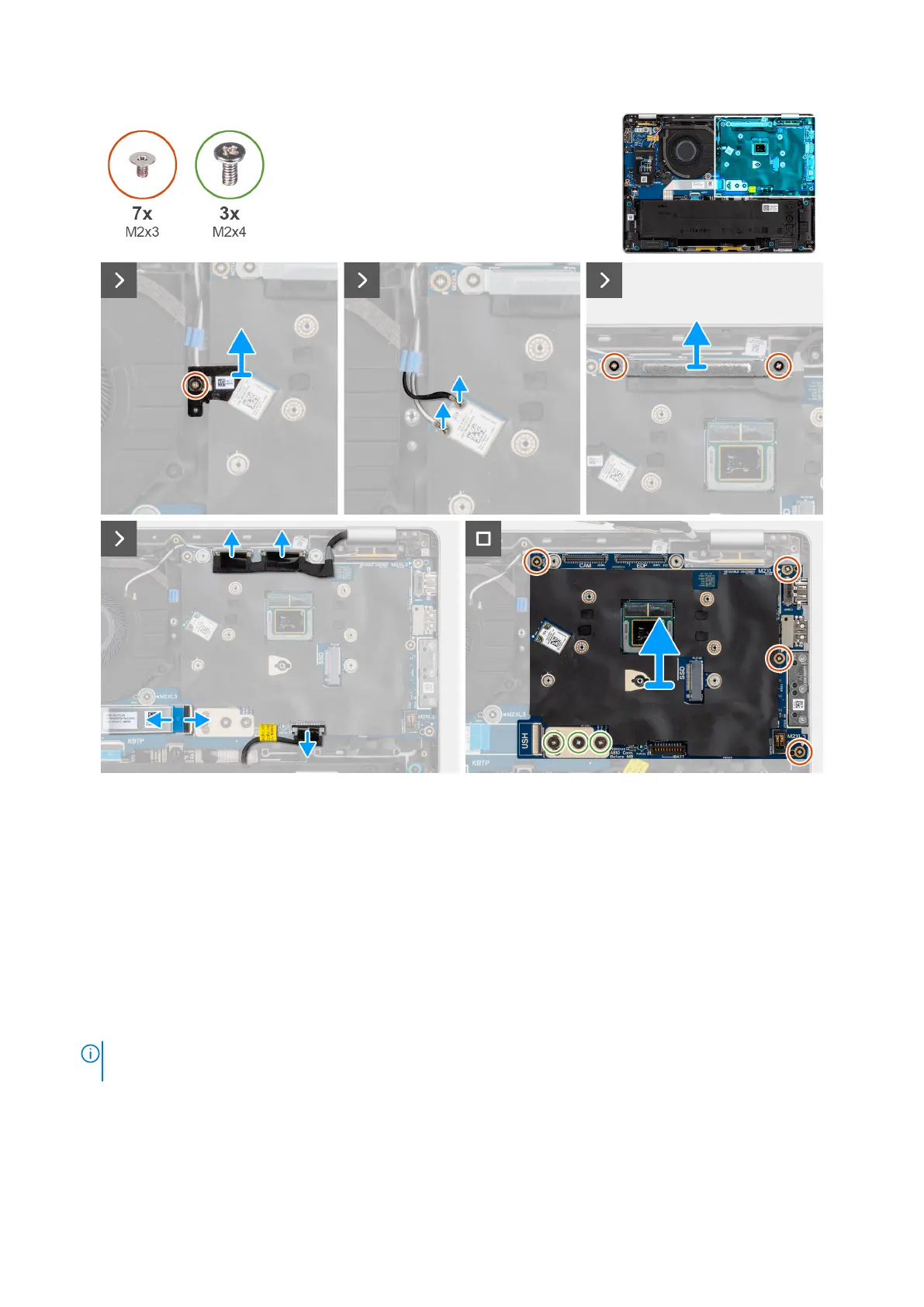
Figure 70. Removing the system board
Steps
1. Remove the screw (M2x3) that secures the WLAN bracket in place.
2. Remove the WLAN bracket from the computer.
3. Disconnect the WLAN antenna cables from the WLAN module on the system board.
4. Remove the two screws (M2x3) screws securing the display bracket in place.
5. Remove the display bracket from the computer.
6. Disconnect the display connector, camera connector, battery cable, and USH board FFC (for models shipped with a USH
daughter board) from the system board.
7. Remove the four screws (M2x3) and three screws (M2x4) securing the system board in place.
8. Remove the system board from the computer.
NOTE:
The USB-C connector module is part of the replacement system board but is also a service part that can be
replaced independently. See the USB-C Connector Module section for more information.
Removing and installing Field Replaceable Units (FRUs) 101