Signal Inputs and Outputs
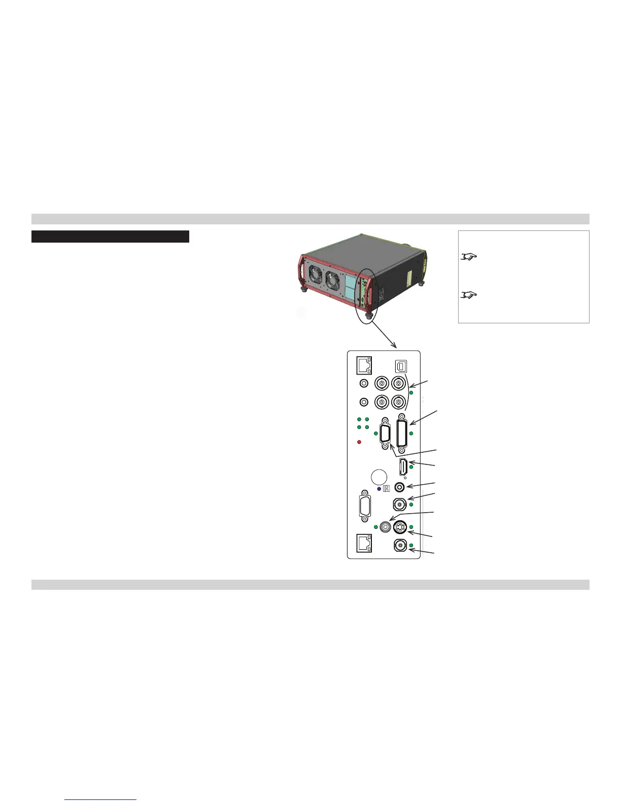
Rear Connection Panel
VGA (input 1)
• Use Auto Setup in the Image/VGA Setup menu. For more settings, see the
Operating Guide.
HDMI (input 2), DVI (input 3)
Analog or Digital DVI-I
• Set DVI-I Port in the Setup/InputConguration menu to choose between Analog
and Digital. For more settings, see the Operating Guide.
SPDIF
• Compatible audio sample packets on the HDMI input stream are decoded by the
projector and output on the SPDIF connector. This is a digital output.
3G-SDI (input 4)
• If two video streams are being transmitted, set 3G Level B Stream in the
Setup/InputConguration menu to choose between the two streams.
CVBS1 (input 5)
• Connect a Composite Video input signal to the BNC connector.
S-Video (input 6)
• Connect to the 4-pin mini-DIN connector.
Component (input 7)
RGsB or RGBS
• Set Component Colour Space in the Setup/InputConguration menu to RGB.
• Set Component Sync Type to Auto, except when the projector has problems
selecting between 3 Wire (RGsB) and 4 Wire (RGBS).
YPbPr
• Set Component Colour Space in the Setup/InputConguration menu to YPbPr.
CVBS2 (input 8)
• Connect a Composite Video input signal to the RCA phono connector.
Component
DVI
VGA
HDMI
SPDIF
CVBS1
CVBS2
S-Video
3G-SDI
Notes
For a complete listing of pin
congurations for all signal and
control connectors, see Wiring
Details later in this Guide.
See the next page for important
information about the differences
between the two connection panels.
Rear Connection Panel

 Loading...