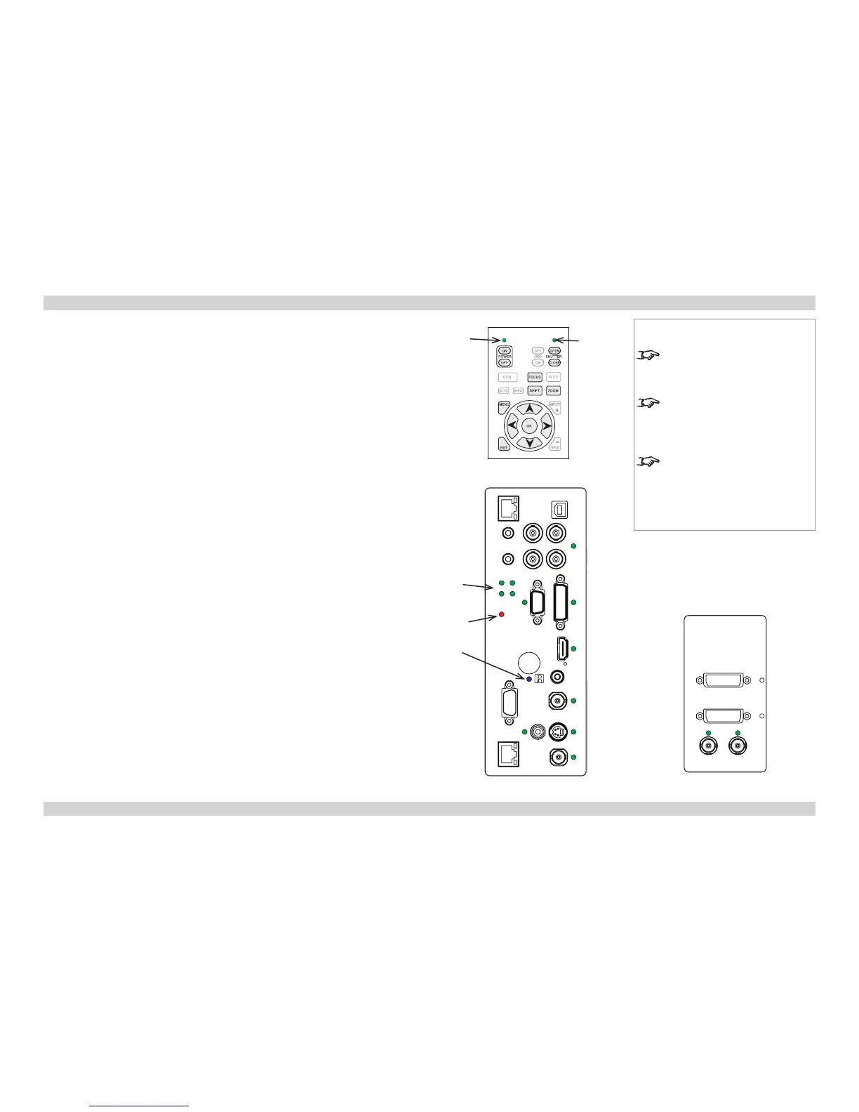
Control panel indicators
The indicators on the control panel are as follows:
Power off = NO POWER
green = normal RUNNING mode amber = STANDBY mode
Shutter amber = CLOSED green = OPEN
Connection panel indicators
The indicators on the rear connection panel are as follows:
All on = Power-On Self Test
Lamps 1-4 off = OFF
green = ON (100%) amber = (80 - 99%)
ashing green = WARM-UP ashing amber = COOL-DOWN
red (projector in standby) = Lamp Comms Error (call service)
red (projector on) = Ballast Comms Error (call service)
ashing red (projector in standby) = Lamp Error on previous operation
ashing red (projector on) = Lamp / Interlock Error
Error ashing = Fan / System Error steady = Voltage Error
IR blue ash = Remote control command received
Inputs The indicators next to the input connectors on both panels are as follows:
off = not selected
green = input selected, signal detected, and in range
ashing green = input selected, but signal not detected or out of range
Power
Shutter
Notes
Only the controls shown highlighted
are used on this projector.
For full details of how to use the
controls and the menu system, see
the Operating Guide.
For more information about
the connection panels, see the
Connection Guide.
Control Panel
Error
Lamps
3 4
1 2
Side Connection Panel
IR
Rear Connection Panel

 Loading...