Appendix D HYBRID Coater Service Manual ver1.1
140
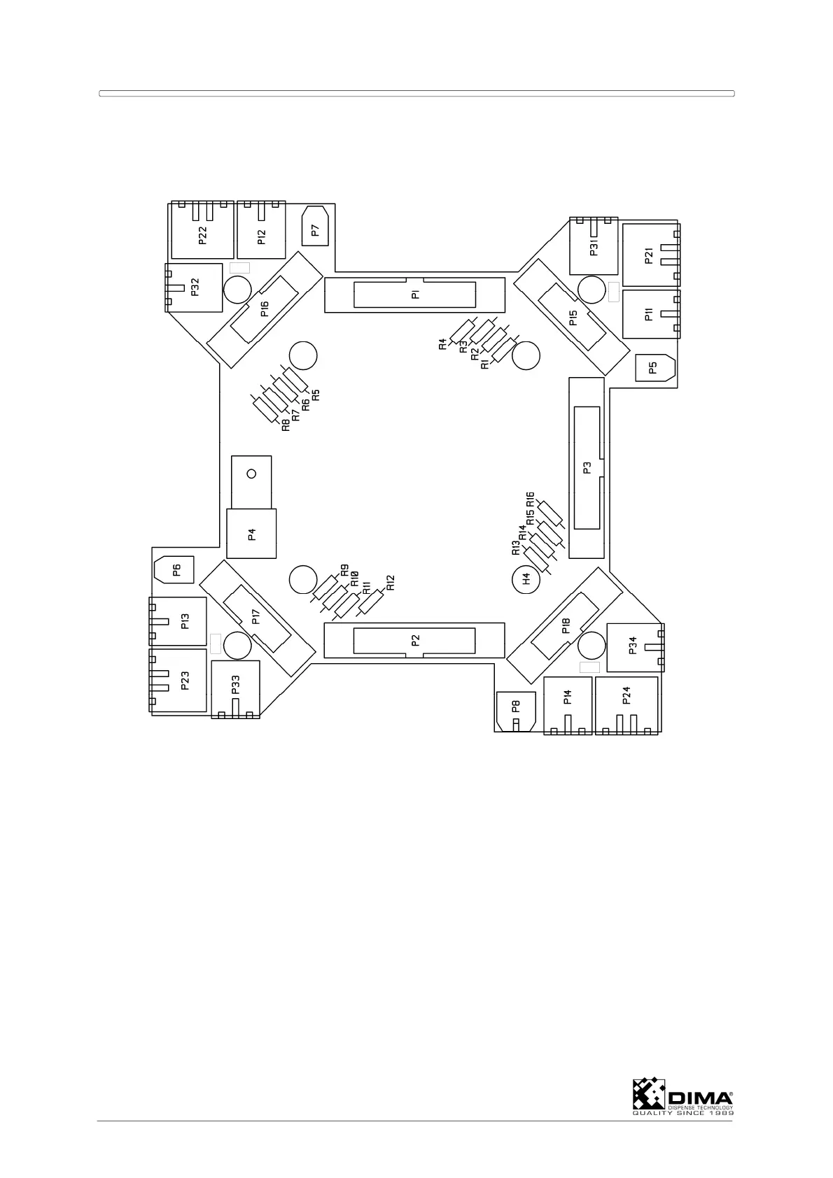
CONNECTOR NUMBERING
Below figure shows the position of the connectors on the PCB.
Some I/O is dedicated for the machine. Other are present for present and future options.
Some of this last I/O is flexible, which means that it can be used as an input which function is
determined by the software running on the Personal Computer.
CONNECTORS P1, P2 AND P3 TO CONNECTION PCB
These connectors are present to connect signals to the EL-04875 Connection PCB.
See wiring diagrams MHC-0200-0108 for more information.
CONNECTORS P15, P16, P17 AND P18 TO CONNECTION PCB
These connectors are not used at this moment.