Appendix E HYBRID Coater Service Manual ver1.1
144
Some I/O is dedicated for the machine. Other are present for present and future options.
Some of this last I/O is flexible, which means that it can be used as an input which function is
determined by the software running on the Personal Computer. See Appendix I for more
information.
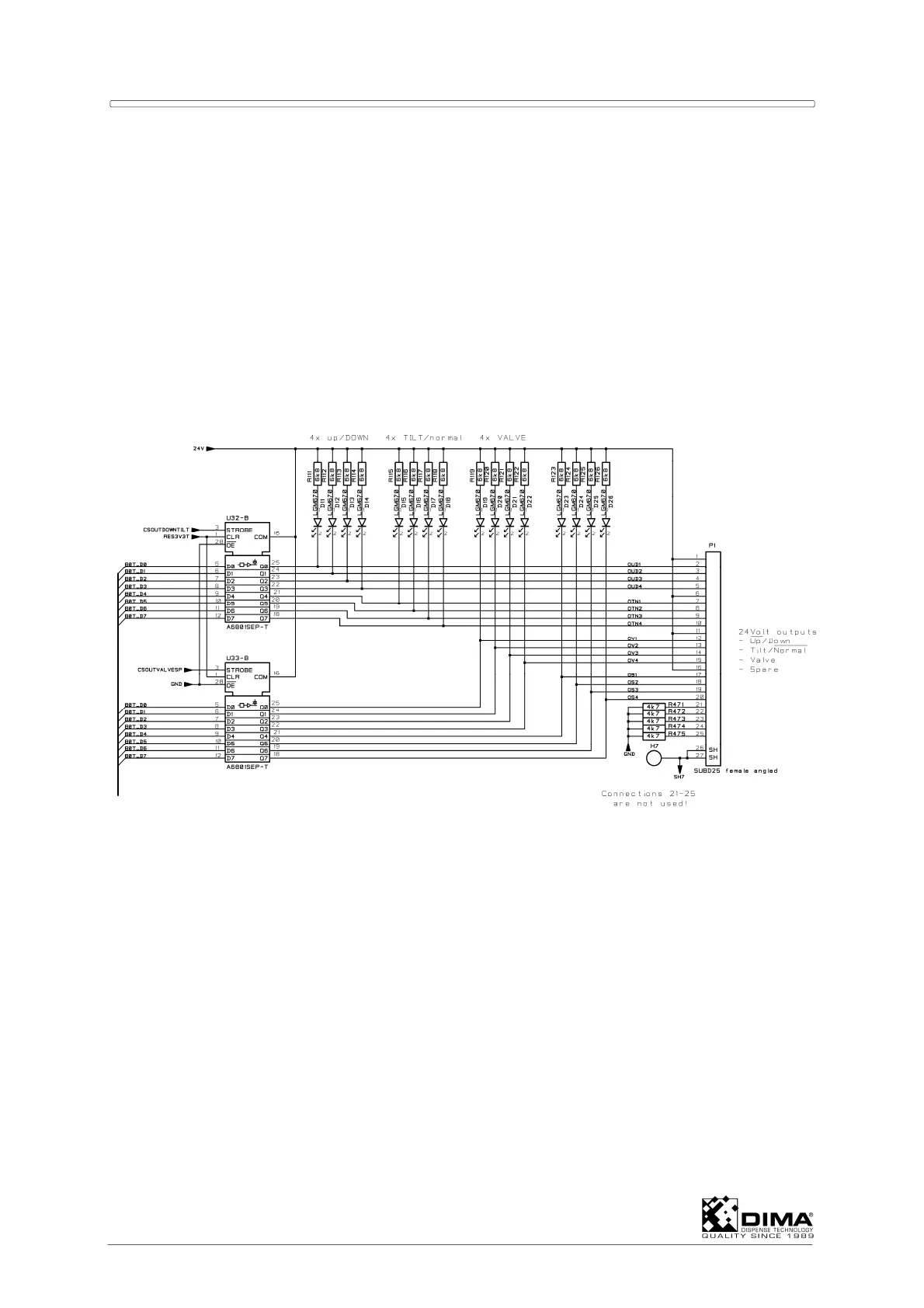
CONNECTOR P1 FOR OUTPUTS DOWN, TILT, VALVE AND SPARE
This connector contains 16 outputs for the valves of above mentioned outputs. These
outputs are used for the valve mount assemblies.
Each output exists of an so called open collector output. This means that the valve for down,
tilt, valve and spare must be connected between 24Volt and the concerning output pin on the
connector. The maximum current of the load is 500mA. Below figure shows the schematics
regarding connector P1.
Connector P1 is connected via cable KHC-0100-0108 to connector P4 of the EL-04875
Connection PCB.
See wiring diagram MHC-0200-0315 and MHC-0200-0107 for HC-100 and MHC-0200-0108
for HC-200 for more information.
CONNECTOR P2 FOR INPUTS UP, DOWN, TILT, NORMAL
This connector is used for connecting the signals of the limits of the valve mount assemblies.
The valve mount assemblies are connected to the Dispense Head PCB (EL-04806 or EL-
04876 for HC-200 and EL-04879 for HC-100). Via Connection PCB EL-04875 the limits are
connected to the EL-04873 Control PCB. All above limits in the machine are reed contacts
with built in LED-indication. Below figure shows the schematics regarding connector P2.