HYBRID Coater Service Manual ver1.1 Appendix E
145
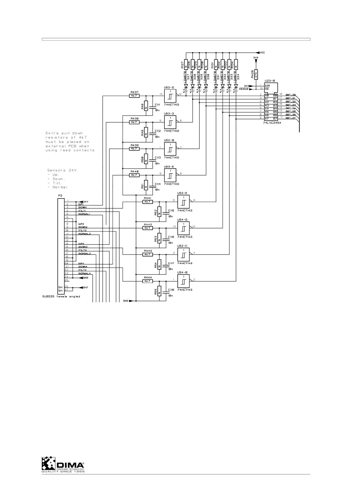
All input circuits are equal. The ones for Tilt and Normal are not visible in above figure. The
extra pull down resistors of 4k7 are present on the Dispense Head PCB.
Connector P2 is connected via cable KHC-0100-0208 to connector P5 of the EL-04875
Connection PCB.
See wiring diagram MHC-0200-0315 and MHC-0200-0107 for HC-100 and MHC-0200-0108
for HC-200 for more information.
CONNECTOR P3 FOR X, Y, Z AND Ø LIMITS AND Ø ENCODER
The connector is used for connecting the signals of the limits of X, Y, Z and Ø. Also the
power supply for and the converted encoder signals are connected to this connector. The
limits and encoder are connected to EL-04875 Connection PCB. For the X, Y and Ø vane
switches are used to detect the limits. The inputs for these sensors need extra series
resistance. These are located on the Connection PCB. The Z sensor needs an extra pull
down resistor. This resistor is also located on the EL-04875 Connection PCB.