M4000 Insulation Analyzer User Guide
72A-1230 Rev. F 3-29
July 22, 2005
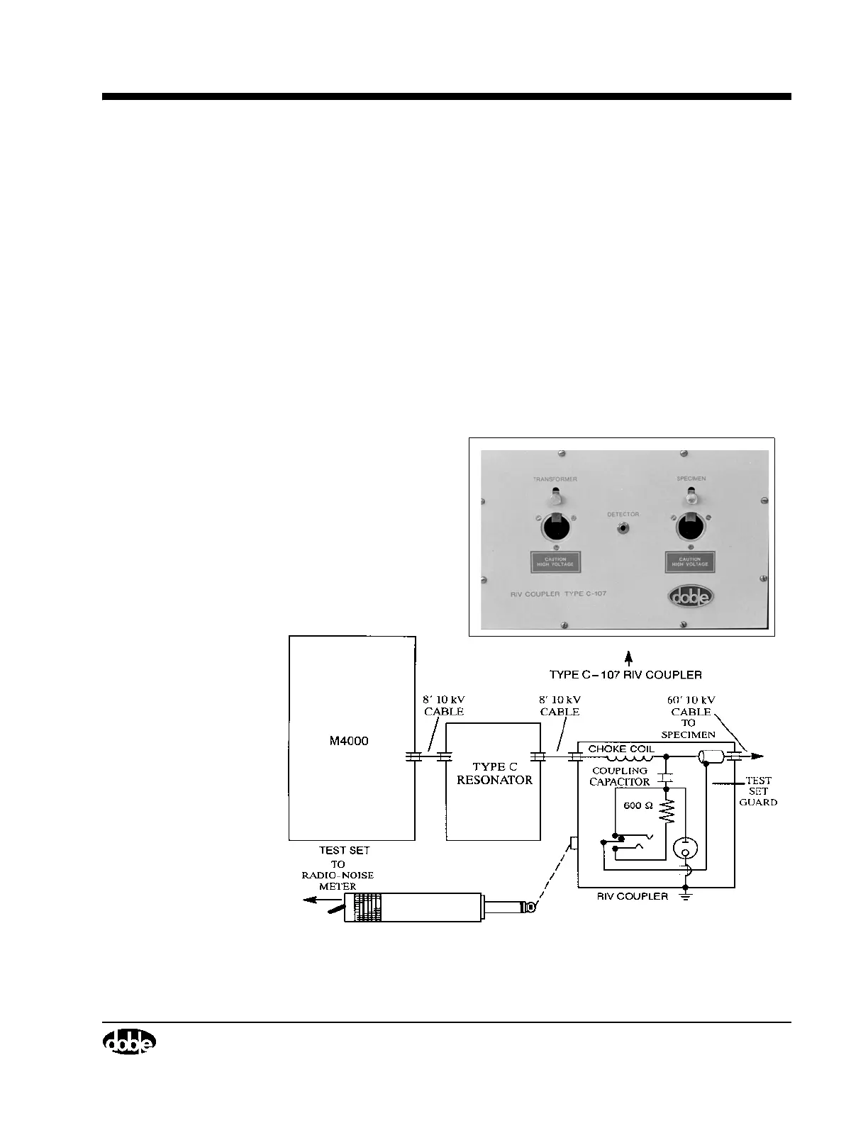
Note that the circuit in Figure 3.19 is so arranged that, when the telephone
plug is removed from the Coupler, the lower terminal of the coupling capacitor
is connected to the test-setguard circuit. In this way, the Coupler may be left
connected for power-factor tests. The telephone plug must be removed or the
capacitor current and losses will be included in the measurement. Note that if
the telephone plug (i.e., the radio-noise meter) is left connected, the Coupler
adds only a small watts loss to the measurement being made. Despite the
shielding, some stray capacitive currents are measured. The stray currents (at
10 kV) may be measured with the Coupler connected for test but with no
specimen connected. For low-capacitance specimens, this current may be
subtracted before the power-factor calculation is made, if it is appreciable
compared with the specimen current.
Figure 3.19 Coupling Arrangement for RIV Measurements with 10 kV Test
Sets
The RIV Coupler is contained
in a metal housing measuring
9¼ x 14½ x 11½ inches, and
weighs approximately 25
pounds.