DOBOT CR5 User Guide 2 Overview
Issue V3.5.3.1 (2020-05-09) User Guide Copyright © Yuejiang Technology Co., Ltd
15
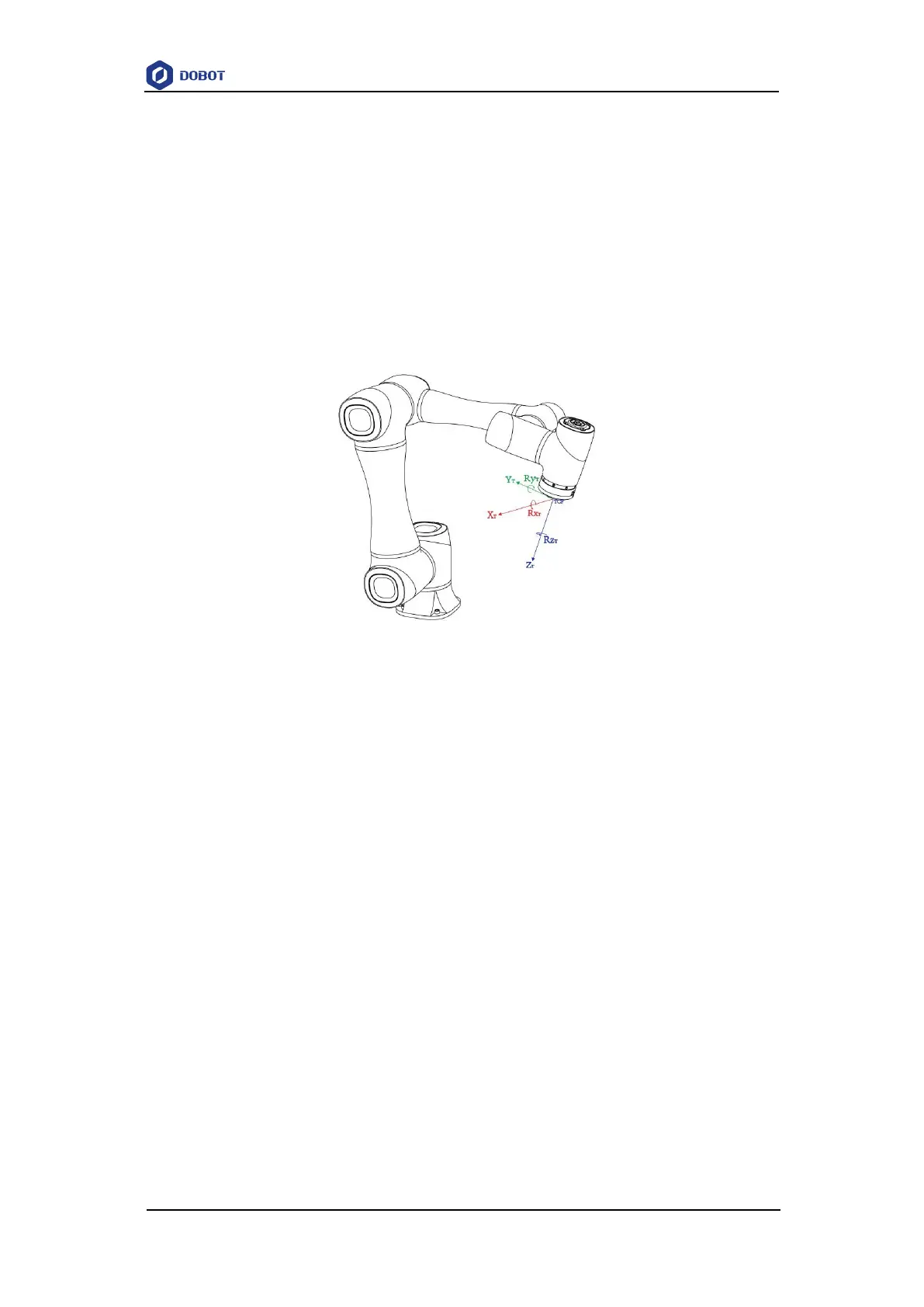
2.5.2.3 Tool Coordinate System
Tool coordinate system is the coordinate system that defines the distance and rotation angle of
the offset, of which the origin and orientations vary with the position and attitude of the workpiece
located at the robot flange. The 10 types of tool coordinate systems can be defined. Tool 0 coordinate
system is the predefined Tool coordinate system which is located at the robot flange without end
effector and cannot be changed. And the others can be customized by users.
Figure 2.14 shows the default Tool coordinate system of a CR5 robot. R
XT
, R
YT
, R
ZT
are the
orientation data, which are designated by rotating the tool center point (TCP) around the X, Y, Z
axes under the default Tool coordinate system.
Figure 2.14 The default Tool coordinate system of CR5 robot
2.5.2.4 User Coordinate System
The User coordinate system is a movable coordinate system which is used for representing
equipment like fixtures, workbenches. The origin and the orientations of axes can be defined based
on site requirements, to measure point data within the workspace and arrange tasks conveniently.
There are totally 10 groups of User coordinate systems, of which the first one is defined as the
Base coordinate system by default and cannot be changed. And the others can be customized by
users.
Figure 2.15 shows the default User coordinate system of a CR5 robot. R
XU
, R
YU
, R
ZU
are the
orientation data, which are designated by rotating the tool center point (TCP) around the X, Y, Z
axes under the selected User coordinate system.