SECTION 6 Field Replaceable Parts
0855855eng 6/08 6–13
2. Route the wire harness back through the wire duct.
3. Install the new ink level sensor to the heat shield, using a 5/8
inch open-end wrench on the top nut and a 9/16 open-end
wrench on the bottom nut.
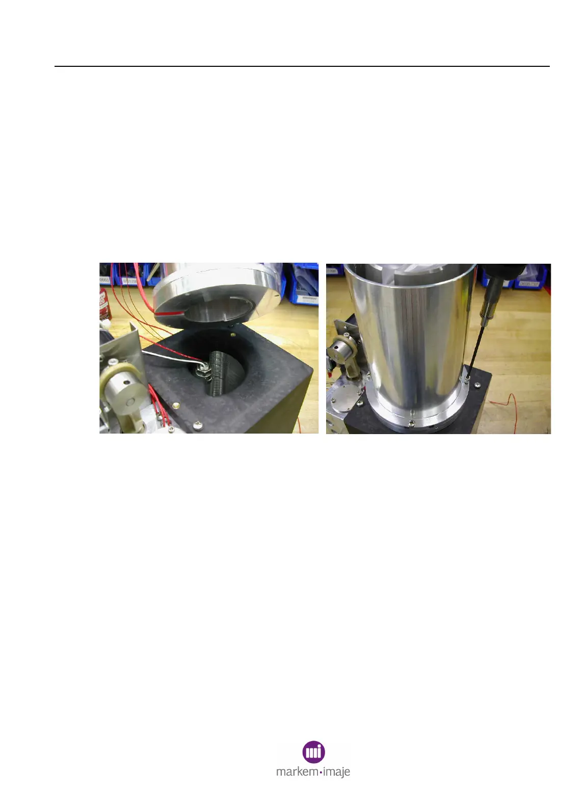
4. Assemble the melt chamber to the heat shield using the two
Allen screws, and tighten. Ensure that there are no pinched
wires between the melt chamber assembly and the heat shield.
See Figure 6-10.
5. Loosen the bottle guide, and slide it up on the melt chamber.
Tighten the bottle guide into place.
6. Install new wire ties to the wire harness.
Figure 6–10
6.5 Final Steps
When paragraphs 5.2 through 5.4 are complete:
1. Install the front cover.
NOTE: The ground wire may need to be connected to the print
station first.
2. Connect the power cable and power on the Model 5200/5400.

 Loading...