EasyManuals Logo

Dover Markem-Imaje 5200 Service Guide

Dover Markem-Imaje 5200
200 pages
To Next Page IconTo Next Page
To Previous Page IconTo Previous Page
Page #116 background imageLoading...
Page #116 background image
SECTION 6 Field Replaceable Parts
6–12 0855855eng 6/08
6.4 Replacement
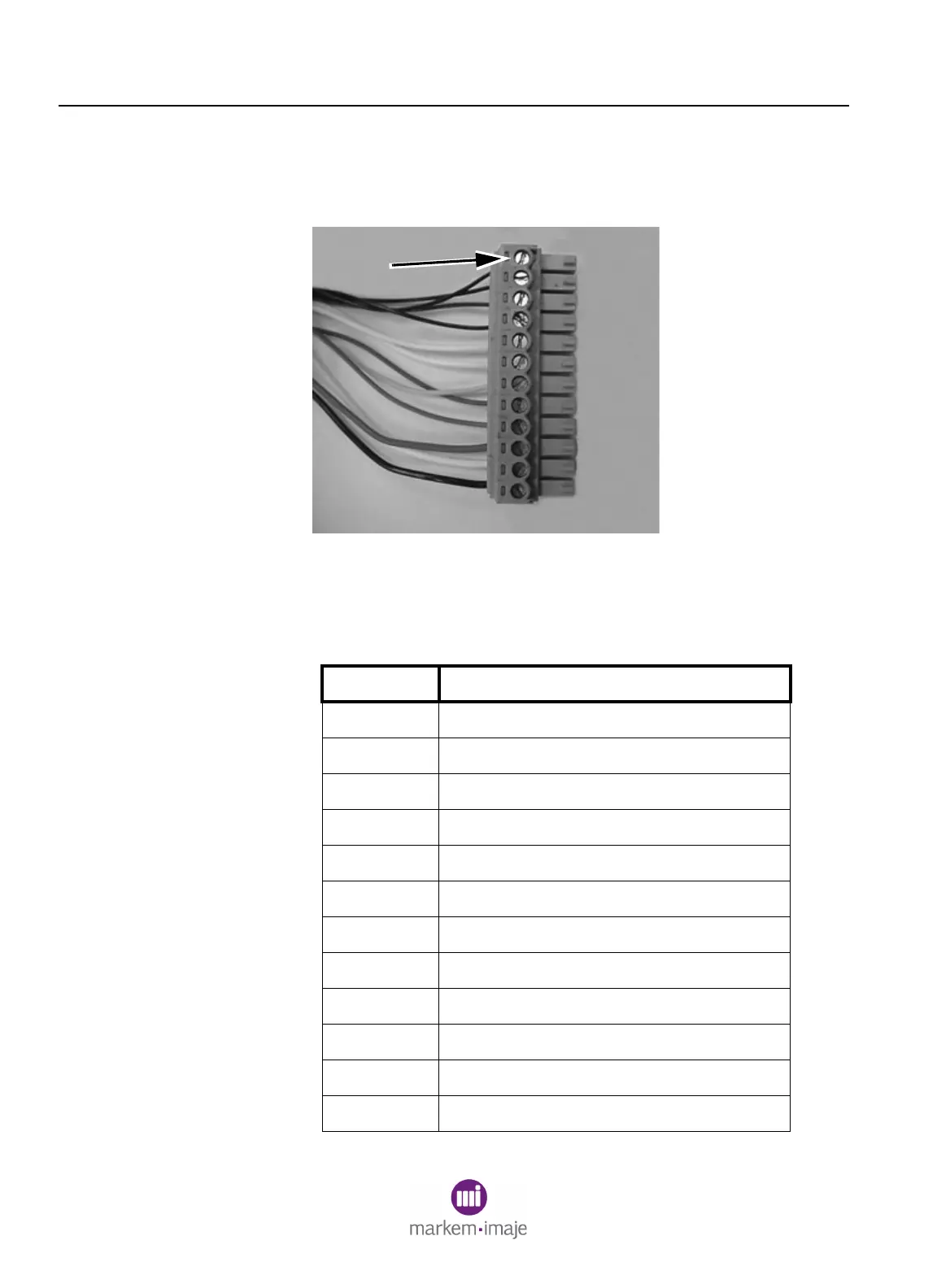
1. Install the wire leads into the appropriate terminals and tighten.
Note Pin #1 (1, FIgure 6-9). Use Table 6-1 for guidance.
Figure 6–9
Table 6–1 IDM Connector Pins
Pin # Function
1
RED MELT THERMISTOR (1, Figure 6-9)
2
RED MELT THERMISTOR
3
RED HOLDING THERMISTOR
4
RED HOLDING THERMISTOR
5
WHITE PUMP SWITCH MIDDLE [NO]
6
WHITE PUMP SWITCH [COM]
7
WHITE PHOTO SENSOR
8
BROWN PHOTO SENSOR
9
BLUE PHOTO SENSOR
10
RED INK LEVEL SENSOR
11
WHITE INK LEVEL SENSOR
12
BLACK INK LEVEL SENSOR
1

Table of Contents

Other manuals for Dover Markem-Imaje 5200

Questions and Answers:

Question and Answer IconNeed help?

Do you have a question about the Dover Markem-Imaje 5200 and is the answer not in the manual?

Dover Markem-Imaje 5200 Specifications

General IconGeneral
BrandDover
ModelMarkem-Imaje 5200
CategoryPrinter
LanguageEnglish

Related product manuals