■■■■■■■■■■■■■■■■■■■■■■■■■■■■■■■■■■■■■■■■■■■■■■■■■■■■■■■■■■■■■■■■■■■■■■■■■■■■■■■■■■■■■■■■■■
▼
Connector Pinouts and LEDs
DS1103 Hardware Installation and Configuration March 2004
161
▲
■■■■■■■■■■I
▲■■■■■■■■■■■■■■■
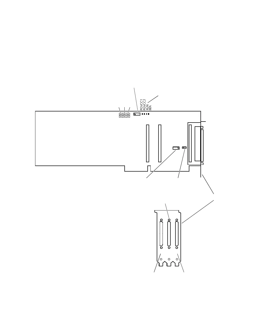
Board Overview
The illustration shows the locations of the connectors, jumpers and
LEDs on the DS1103. It is not to scale.
P1P2P3
S1-1 S1-2
S1-3
1
1
1
JTAG programming connector (P5)
Slave DSP debug
connector (P6)
Incremental encoder/
digital connector (P3)
Slave DSP
flash jumpers (J1)
Digital connector (P2)
Analog
connector (P1)
(P3) (P2)
Status LEDs
(P1)
Bracket
 Loading...
