Installing the Hardware
▲
■■■■■■■■■■■■■■■■■■■■■■■■■■■■■■■■■■■■■■■■■■■■■■■■■■■■■■■■■■■■■■■■■■■■■■■■■■■■■■■■■■■■■■■■■■■■■■■■
DS1103 Hardware Installation and Configuration March 2004
I■■■■■■■■■■■■■
▼
46
■■■■■■■■■■■■■■■▼
How to Mount a Panel in a 19'' Rack
The connector and LED panels are installed in a desktop box made
from aluminum profiles as a standard. They can optionally be mounted
in a 19’’ industry rack.
Preconditions ■ The system is switched off. For instructions, refer to How to Switch
Off a dSPACE System on page 39.
■ All connections to external devices are removed.
Method To mount panels in a standard 19’’ industry rack
1 Remove the aluminum box. To do so, unscrew one of its side
panels (4 screws). If there is a ribbon cable strain relief at the
bottom of the box, it must be cut open.
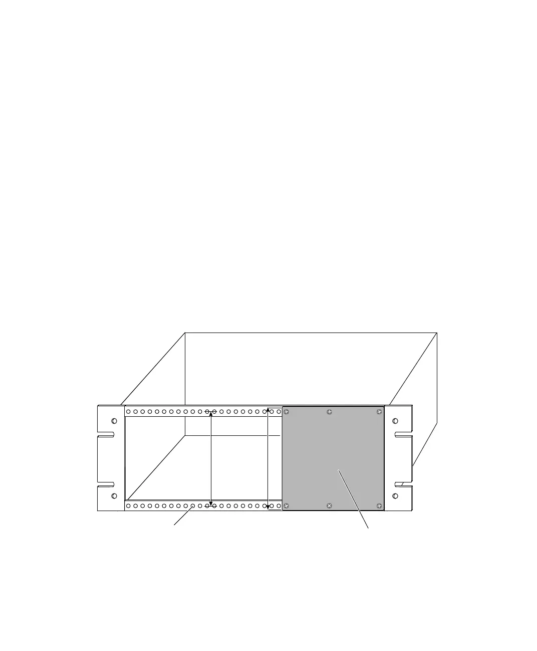
2 Bolt the panel to the front of a 19’’ rack as shown below.
Depending on the rack used, several M2.5x10 or M3x10 bolts are
required.
122.5 mm
(4.82 inch)
128.5 mm
(5.06 inch)
Panel
M2.5 or M3 threads
5 mm (0.2 inch) spacing
Panel is attached by
M2.5x10 or M3x10 bolts
 Loading...
