■■■■■■■■■■■■■■■■■■■■■■■■■■■■■■■■■■■■■■■■■■■■■■■■■■■■■■■■■■■■■■■■■■
▼
Connecting an Expansion Box to the Host PC
DS1103 Hardware Installation and Configuration March 2004
61
▲
■■■■■■■■■■I
▲■■■■■■■■■■■■■■■
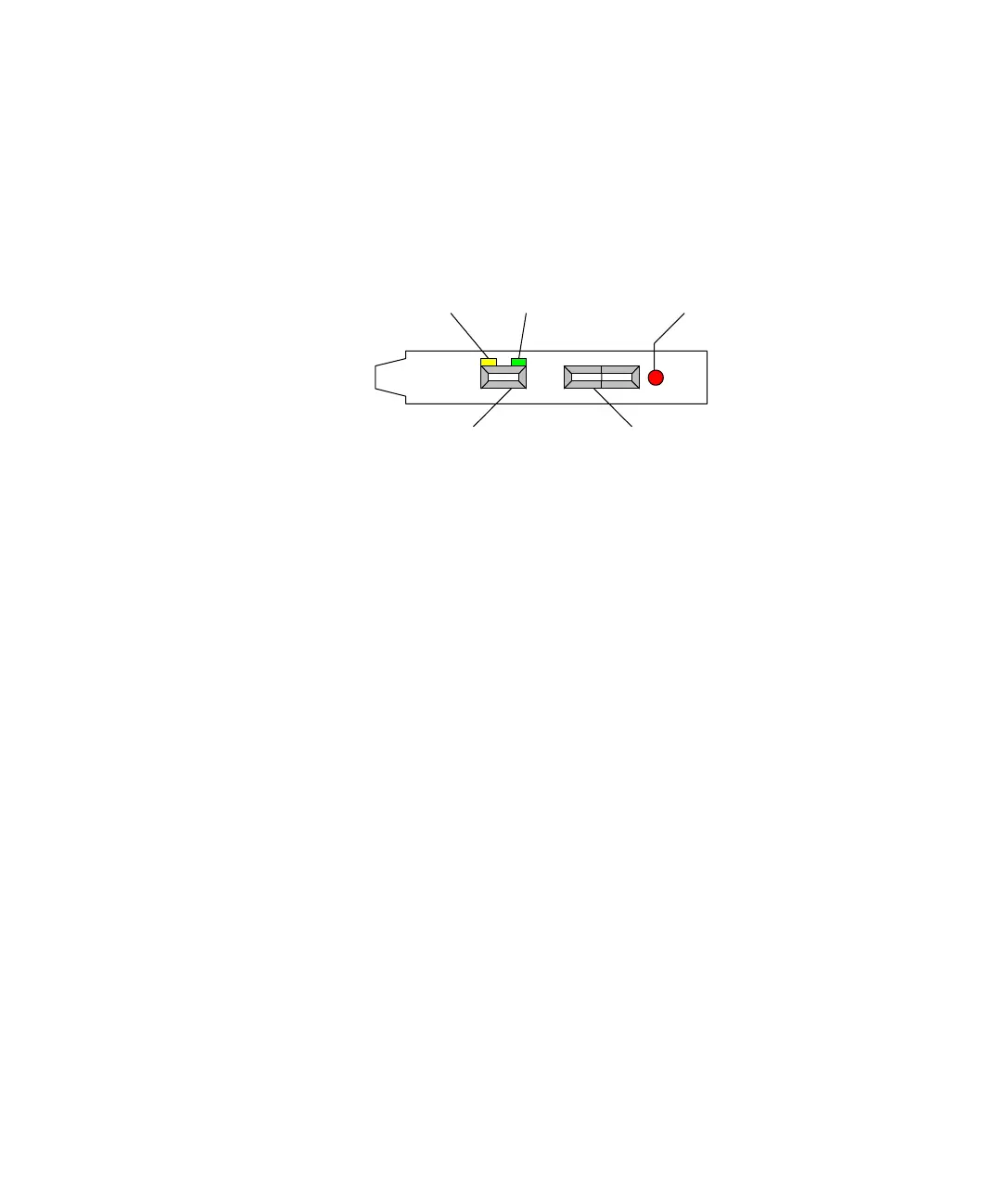
Identifying the Connection Status
DS813, DS814, DS817 Three LEDs on the brackets of the DS813, DS817 and DS814 indicate
the current status of the connection.
Yellow LED A lit yellow LED indicates that the connection between
the host PC and the expansion box is ready for communication.
Red LED A lit red LED indicates that the active connection between
the host PC and the expansion box uses a fiber-optic cable.
Green LED A lit green LED indicates that data is being sent or
received.
DS815 The DS815 is not equipped with optical status indicators. Using the
DS815-RJ45 adapter cable, you can identify the current status of the
connection by the two LEDs integrated in the shell of the RJ45
connector. For details, refer to DS815-RJ45 adapter cable on page 60.
redyellow green
patch cable
connector
fiberoptic
connector
 Loading...
