Connector Pinouts and LEDs
▲
■■■■■■■■■■■■■■■■■■■■■■■■■■■■■■■■■■■■■■■■■■■■■■■■■■■■■■■■■■■■■■■■■■■■■■■■■■■■■■■■■■■■■■■■■
DS1103 Hardware Installation and Configuration March 2004
I■■■■■■■■■■■■■
▼
188
■■■■■■■■■■■■■■■▼
Slave DSP UART RS232 Connector (CP41)
The slave DSP UART RS232 connector (CP41) is a 9-pin male Sub-D
connector located on the front of the connector panel. The pinout has
been adopted from the 9-pin RS232 connector of a PC.
N
The slave DSP of the DS1103 supports one serial communication
interface. In RS232 mode the signals are available from the slave DSP
UART RS232 connector (CP41). In RS422 mode the signals are
available from the slave DSP UART RS422 connector (CP43). CP41 and
CP43 are mutually exclusive and cannot be used at the same time.
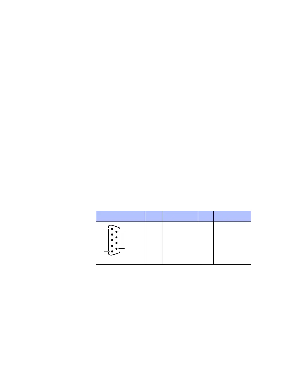
Pinout Because the pin numbering used for Sub-D connectors is not
standardized, the following figure shows the numbering scheme used
(front view).
C
Do not rely on the numbers written on Sub-D connectors.
Connector (CP41) Pin Signal Pin Signal
5GND
4 Not used 9 Not used
3 STXD 8 Not used
2 SRXD 7 Not used
1 Not used 6 Not used
5
1
6
9
 Loading...
