■■■■■■■■■■■■■■■■■■■■■■■■■■■■■■■■■■■■■■■■■■■■■■■■■■■■■■■■■■■■■■■■■■■■■■■■■■■■■■■■■■■■■■■■■■
▼
Connector Pinouts and LEDs
DS1103 Hardware Installation and Configuration March 2004
185
▲
■■■■■■■■■■I
▲■■■■■■■■■■■■■■■
Incremental Encoder Interface
Connectors (CP32 ... CP37, CP39)
The incremental encoder interface connectors (CP32 ... CP37 and
CP39) are 15-pin, female Sub-D connectors located on the front of the
connector panel. Each of the connectors provides the signals for one
of the seven available incremental encoder channels.
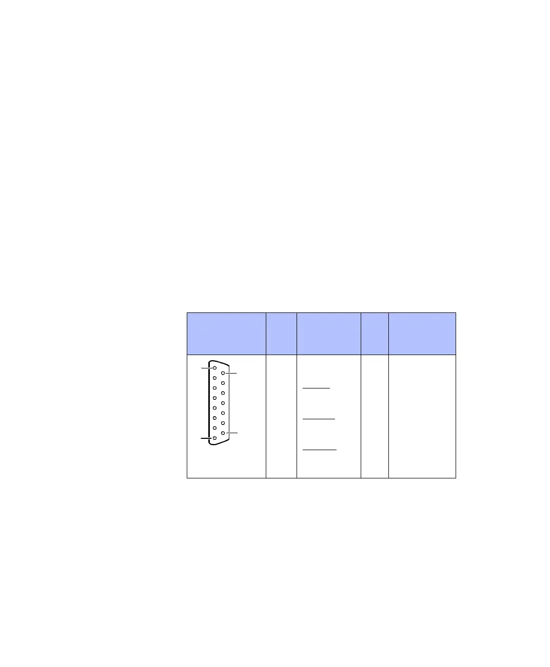
Pinout Because the pin numbering used for Sub-D connectors is not
standardized, the following figure shows the numbering scheme used
(front view).
C
Do not rely on the numbers written on Sub-D connectors.
x corresponds to the seven available incremental encoder channels:
The channels 1 ... 7 correspond to the connectors CP32 ... CP37 and
CP39.
Connector
(CP32 … CP37,
CP39) Pin Signal Pin Signal
1 VCC (+5 V)
2 PHI0(x) 9 VCC (+5 V)
3P
HI0(x) 10 GND
4 PHI90(x) 11 GND
5P
HI90(x) 12 GND
6 INDEX(x) 13 GND
7I
NDEX(x) 14 GND
8GND 15GND
1
8
15
9
 Loading...
