Connector Pinouts and LEDs
▲
■■■■■■■■■■■■■■■■■■■■■■■■■■■■■■■■■■■■■■■■■■■■■■■■■■■■■■■■■■■■■■■■■■■■■■■■■■■■■■■■■■■■■■■■■
DS1103 Hardware Installation and Configuration March 2004
I■■■■■■■■■■■■■
▼
184
■■■■■■■■■■■■■■■▼
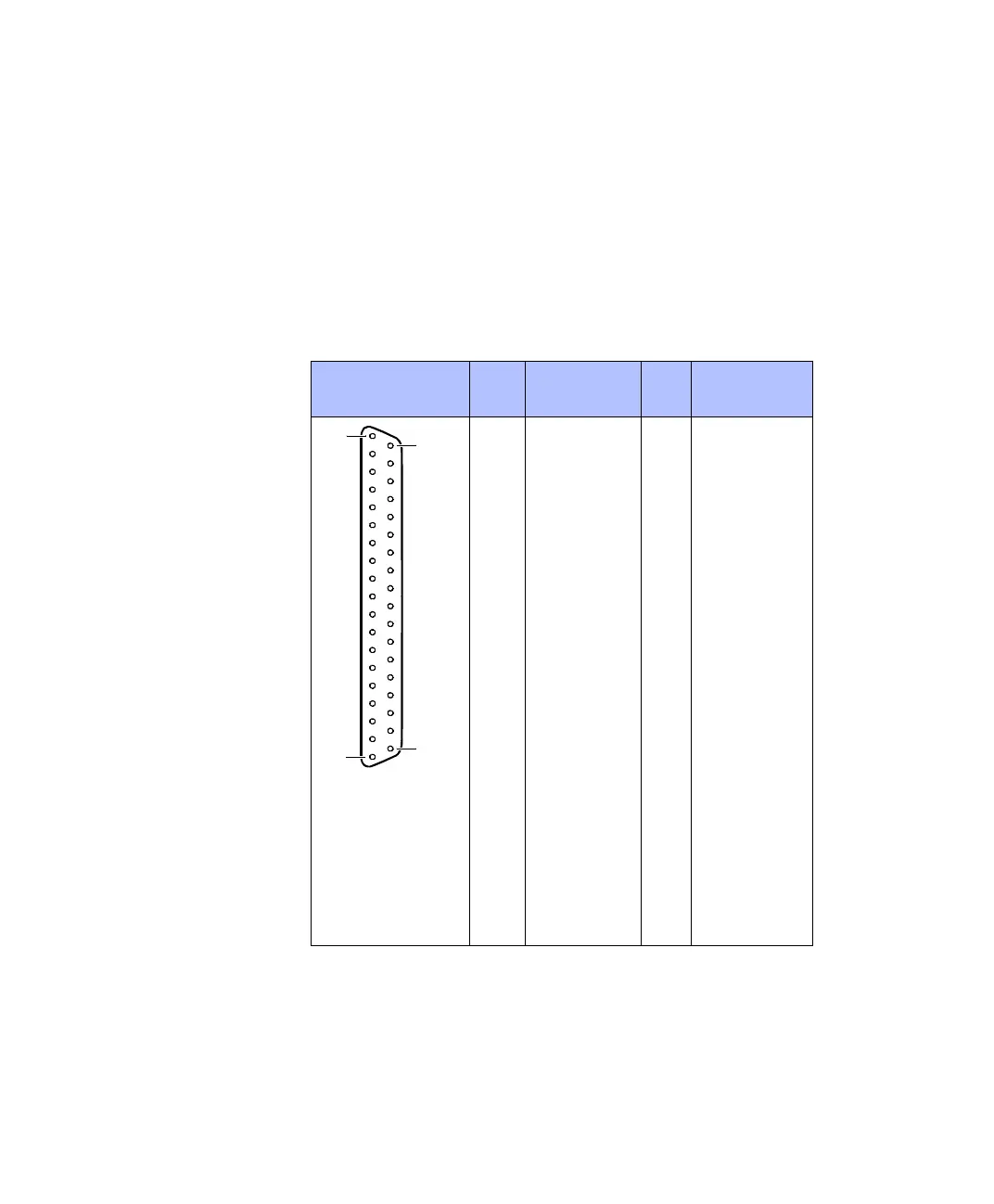
Pinout Because the pin numbering used for Sub-D connectors is not
standardized, the following figure shows the numbering scheme used
(front view).
C
Do not rely on the numbers written on Sub-D connectors.
N
All VCC1, VCC2 and VCC3 lines of the DS1103 are connected on the
CP1103/CLP1103 and called VCC. The total load of all connector pins
that provide access to the PC power supply must not exceed 1.5 A
(CP1103) or 0.75 A (CLP1103).
Slave I/O
Connector (CP31)
Pin Signal Pin Signal
1GND
2 SCAP1 20 GND
3 SCAP3 21 SCAP2
4 GND 22 SCAP4
5 ST2PWM 23 ST1PWM
6 GND 24 ST3PWM
7SPWM1 25GND
8 SPWM3 26 SPWM2
9 SPWM5 27 SPWM4
10 SPWM7 28 SPWM6
11 SPWM9 29 SPWM8
12 STMRCLK 30 GND
13 GND 31 STMRDIR
14 STINT1 32 SPDPINT
15 GND 33 STINT2
16 SSIMO 34 SSOMI
17 SCLK 35 SSTE
18 SXF 36 SBIO
19 VCC (+5 V) 37 GND
1
37
20
19
 Loading...
