Connector Pinouts and LEDs
▲
■■■■■■■■■■■■■■■■■■■■■■■■■■■■■■■■■■■■■■■■■■■■■■■■■■■■■■■■■■■■■■■■■■■■■■■■■■■■■■■■■■■■■■■■■
DS1103 Hardware Installation and Configuration March 2004
I■■■■■■■■■■■■■
▼
178
■■■■■■■■■■■■■■■▼
CP1103/CLP1103 Connectors
The connector panels CP1103 and CLP1103 provide easy-to-use
connections between the DS1103 and devices to be connected to it.
Devices can be individually connected, disconnected or interchanged
without soldering. This simplifies system construction, testing and
troubleshooting.
N
Prior to connecting external devices to the connector panel, ensure
you have familiarized yourself with the relevant instructions provided
in How to Connect External Devices to a Connector Panel on
page 140.
C
WARNING! Hazardous voltages.
Risk of electric shock and/or damage to the hardware.
■ Do not connect any high-voltage devices to the I/O connectors of
the panel.
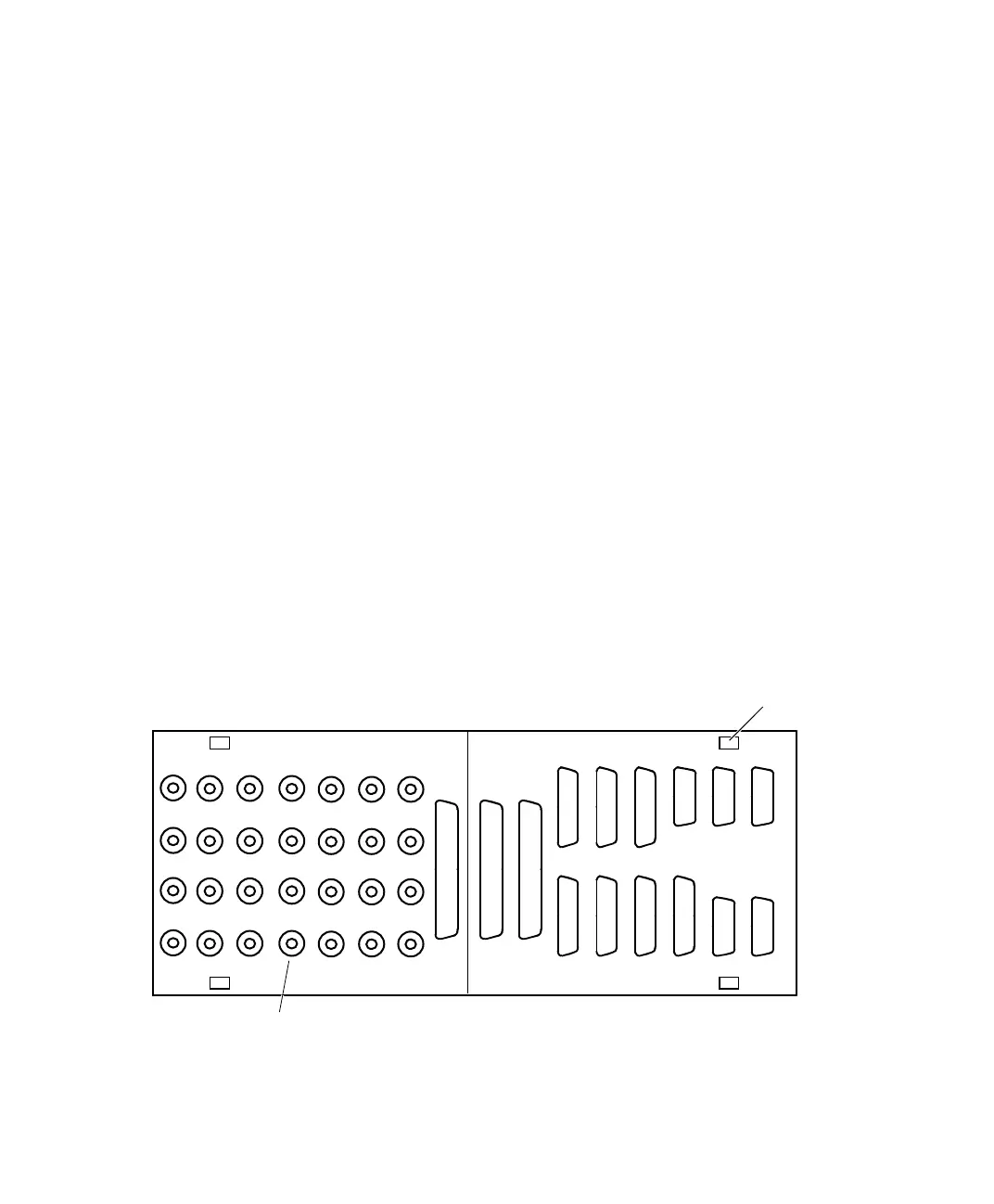
BNC connectors
CP17
CP18
CP19
CP20
CP25
CP26
CP27
CP28
CP1
CP2
CP3
CP4
CP5
CP6
CP7
CP8
CP9
CP10
CP11
CP12
CP13
CP14
CP15
CP16
CP21
CP22
CP23
CP24
Template clip
CP29 CP30 CP31
CP32 CP34 CP36
CP33 CP35 CP37
CP38 CP40 CP42
CP39 CP41 CP43
 Loading...
