Connecting an Expansion Box to the Host PC
▲
■■■■■■■■■■■■■■■■■■■■■■■■■■■■■■■■■■■■■■■■■■■■■■■■■■■■■■■■■■■■■■■■■■
DS1103 Hardware Installation and Configuration March 2004
I■■■■■■■■■■■■■
▼
64
■■■■■■■■■■■■■■■▼
Status LEDs The DS830 is equipped with status LEDs: see Identifying the
Connection Status on page 66.
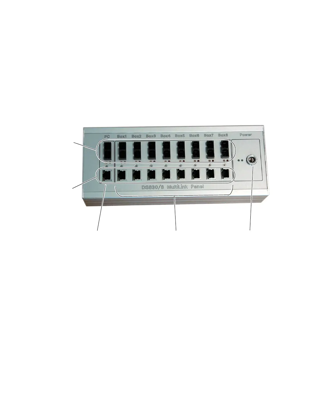
How to Install DS830
The front of the DS830 panel provides all the connectors required for
installation. The following illustration shows the front of the DS830/8.
To install the DS830, you have to connect it to the host PC and the
dSPACE boxes, and supply power to the panel.
To connect the DS830
1 Connect the DS830 to the host PC.
2 Connect the DS830 to the dSPACE boxes (expansion box and/or
MicroAutoBoxes).
N
Use only the cable (fiber-optic or patch cable) supplied with the
dSPACE hardware package.
The DS830 hardware package also includes the cables for connecting
the DS830 to the power supply.
Connection
to dSPACE boxes
Connection
to host PC
Connection
to power supply
Fiber-optic
connectors
Patch cable
connectors
 Loading...
