Connector Pinouts and LEDs
▲
■■■■■■■■■■■■■■■■■■■■■■■■■■■■■■■■■■■■■■■■■■■■■■■■■■■■■■■■■■■■■■■■■■■■■■■■■■■■■■■■■■■■■■■■■
DS1103 Hardware Installation and Configuration March 2004
I■■■■■■■■■■■■■
▼
186
■■■■■■■■■■■■■■■▼
N
All VCC1, VCC2 and VCC3 lines of the DS1103 are connected on the
CP1103/CLP1103 and called VCC. The total load of all connector pins
that provide access to the PC power supply must not exceed 1.5 A
(CP1103) or 0.75 A (CLP1103).
N
If the encoder has SENSE lines, connect SENSE+ to VCC (Pin 9) and
SENSE– to GND (Pin 15).
CAN Connector (CP38)
The CAN connector (CP38) is a 9-pin, male Sub-D connector located
on the front of the connector panel. The pinout has been adopted
from the standard, 9-pin CAN connector.
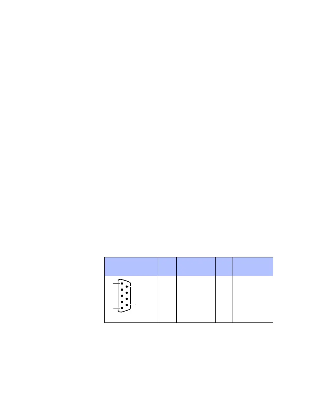
Pinout Because the pin numbering used for Sub-D connectors is not
standardized, the following figure shows the numbering scheme used
(front view).
C
Do not rely on the numbers written on Sub-D connectors.
N
The CAN bus lines (CANH, CANL) are not terminated with a resistor on
the DS1103.
CAN Connector
(CP38)
Pin Signal Pin Signal
5GND
4 Not used 9 Not used
3GND 8Not used
2 CANL 7 CANH
1Not used 6GND
5
1
6
9
 Loading...
