Connecting an Expansion Box to the Host PC
▲
■■■■■■■■■■■■■■■■■■■■■■■■■■■■■■■■■■■■■■■■■■■■■■■■■■■■■■■■■■■■■■■■■■
DS1103 Hardware Installation and Configuration March 2004
I■■■■■■■■■■■■■
▼
60
■■■■■■■■■■■■■■■▼
T
DS815 boards delivered before November 2001 have a blue label.
Boards delivered later have a red label, or a blue label with “Vs. 2.0“.
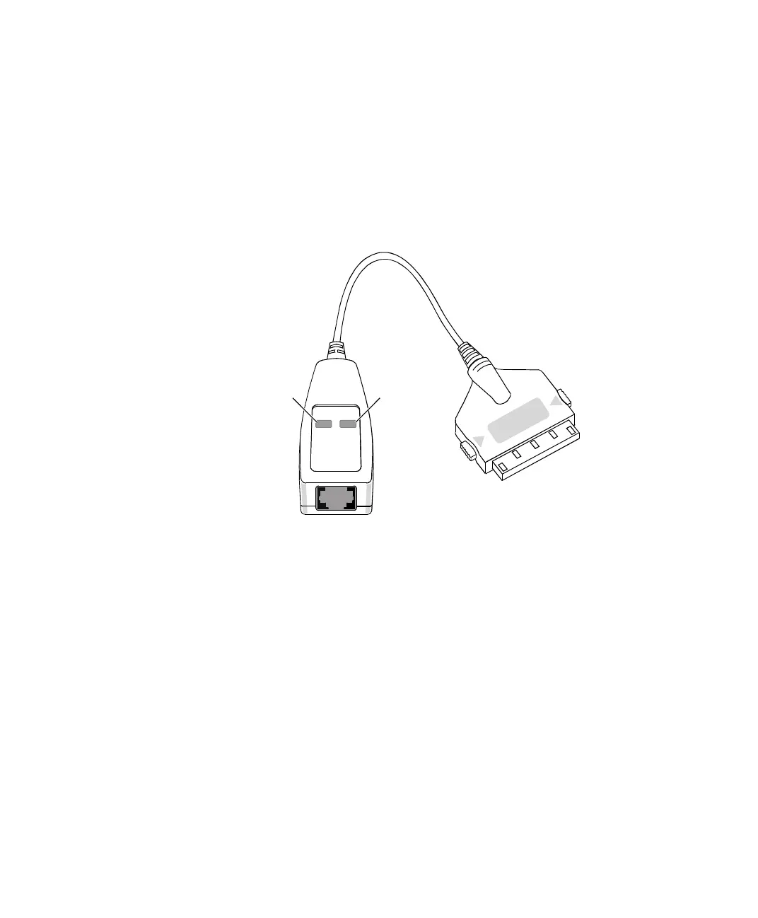
DS815-RJ45
adapter cable
An adapter cable is available for the new DS815 connector to adapt
the DS815 to a standard patch cable with an RJ45 connector. The
adapter cable is labeled “DS815-RJ45 Vs 2.0”.
Two LEDs indicate the current status of the connection.
Yellow LED A lit yellow LED indicates that the connection between
the host PC and the expansion box is ready for communication.
Green LED A lit green LED indicates that data is being sent or
received.
N
For the connection between the DS815-RJ45 adapter cable and the
DS814 Link Board (Box), you must use a crossed-over patch cable.
LED (yellow) LED (green)
 Loading...
