Installing the Hardware
▲
■■■■■■■■■■■■■■■■■■■■■■■■■■■■■■■■■■■■■■■■■■■■■■■■■■■■■■■■■■■■■■■■■■■■■■■■■■■■■■■■■■■■■■■■■■■■■■■■
DS1103 Hardware Installation and Configuration March 2004
I■■■■■■■■■■■■■
▼
48
■■■■■■■■■■■■■■■▼
C
CAUTION! Even a brief disconnection of the battery while the
engine is running results in a load dump of the car generator
producing hazardous voltages of more than 100 V.
■ Turn off the engine while connecting or disconnecting the car
battery.
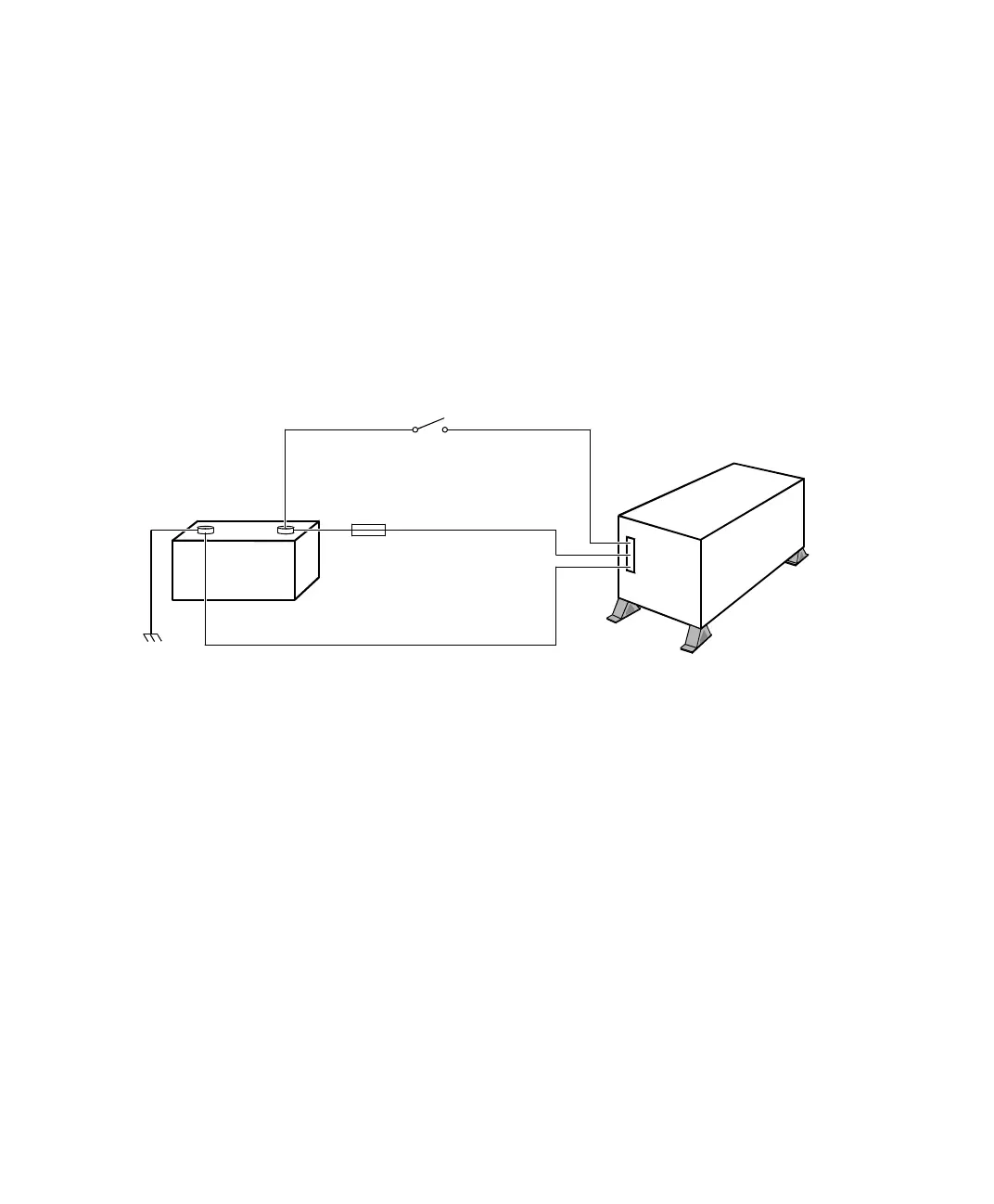
Wiring diagram The wiring has to be performed according to the illustration below. If
you use TandemAutoBox both power supplies must be connected.
N
■ The remote voltage should not exceed the supply voltage.
Overvoltage protection of the remote pin is 100 V.
■ The remote voltage may be used for starting AutoBox with a
remote switch: KL15, for example (output of the ignition/driving
switch).
■ If you connect the remote pin to the car battery directly, the
AutoBox will always be turned on, and the car battery will soon be
exhausted if the engine is not running. Thus, a switch is highly
recommended.
Car battery
(+) red wire to pin A2
60 A fuse
(close to battery)
+
–
AutoBox
Remote to pin 4
(-) unmarked wire to pin A1Car chassis
 Loading...
