WinAQMS Mini DAS User manual 1.0 Edit Menu
27
(DO): These fields are used when sending digital
signals to the instrument. The digital signals
can be set to either high, low or empty and
should match up to the requirements of the
instrument (see section 6.3 Communicate with
Analyser). Click repeatedly on the cells to
change their values.
Instruments: Instruments that are being used for calibrations
can appear in this section (9830, 9841 etc) these
fields should have the function being performed
to them at this specific point.
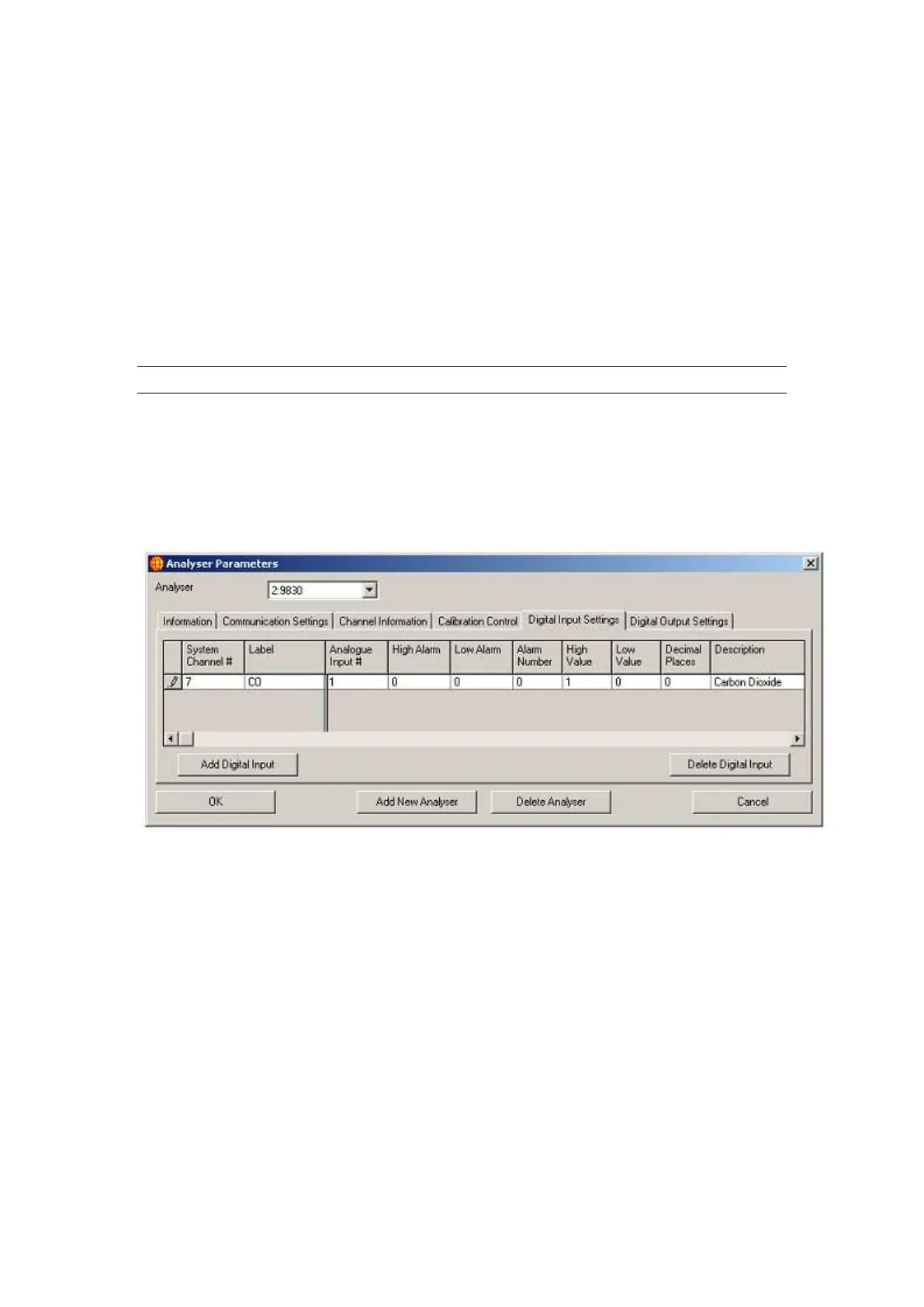
4.2.5 Digital Input and Output settings
The Digital Input Settings (Figure 27) and Digital Output Settings (Figure 28) Tabs
show the digital input and output points and their settings for the currently selected
analyser. The High Value and Low Value fields show the value that is recorded into
the database for the digital input and output channels when they are high or low; all
other fields have the same function as described in Channel Information. The Add
Digital Input/Output buttons and the Delete Digital Input/Output buttons also function
identically to the Add Channel and Delete Channel buttons in Channel Information.
Figure 27 Digital Input Settings in Analyser Parameters
The Default Output field in Digital Output Settings is the value that the digital output
is set to when WinAQMS Mini DAS is started.