Edit Menu WinAQMS Mini DAS User manual 1.0
26
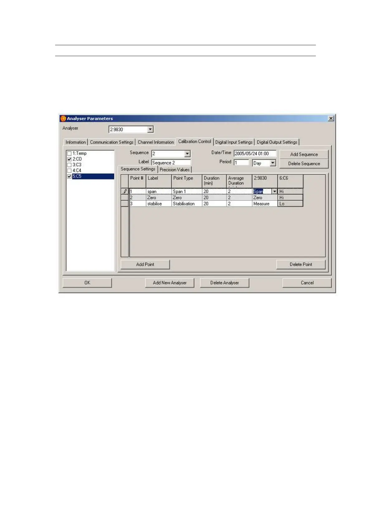
4.2.4 Calibration Control
The Calibration Control tab shows the signals that the digital output channels and
calibrators are set to when the channels of the selected analyser enter the span, zero
and stabilisation periods of their calibration sequence. Each row (point) of the grid
matches a part of a sequence occurring within the analyser. Measurements are only
taken during the Span and Zero cycles, the stabilisation point is a recovery cycle.
Figure 26 Calibration Control in Analyser Parameters
Point: This is one part of a sequence of events that are
performed during a calibration
Label: This is the name you give a specific point so
that it is instantly recognisable and unique
Point type: The drop down field contains the name of the
process that the point will perform (span, zero,
stabilise)
Duration: This is the length of time that each point will
perform there function (minutes)
Average duration
(min): This is the length of time that the measurement
will take place and is displayed as a average
over that time i.e. if set to 2 as in Figure 26 then
readings will be taken over minutes 18 to 20
and the average measurement over this time
will be recorded.
Extra fields
Digital Outputs