55Installation and Service Guide: Color Controller E-85
Replacing parts
The E-85 is shipped from the factory with a standard board configuration, as shown in Figure on page 46. If an optional
component has been installed, see the documentation that accompanies the option kit.
Printer interface board
The printer interface board is a custom board connected to the motherboard. It processes image data and allows the E-85 to
communicate with the printer.
For information about the location of this board on the motherboard, see page 56.
Figure 30: Printer interface board assembly
To remove the printer interface board
When you handle electronic components, follow electrostatic discharge precautions (see page 10).
1 Shut down the E-85, remove all cables from the back, and open the E-85 (see page 48).
2 Remove the screws that secures the board’s mounting bracket to the connector panel and save them for later.
3 Gently pull the board out its connector on the motherboard and place it in an antistatic bag.
To install the printer interface board
When you handle electronic components, follow electrostatic discharge precautions (see page 10).
1 Insert the board into the PCIE_4 connector on the motherboard (see Figure 32 on page 58).
The component side of the board must face down, toward the base of the chassis. The board connector is keyed to fit
only one way.
When reseating the board, be careful not to disturb any motherboard cables that are installed nearby.
2 Attach the board to the connector panel with the screws you removed earlier.
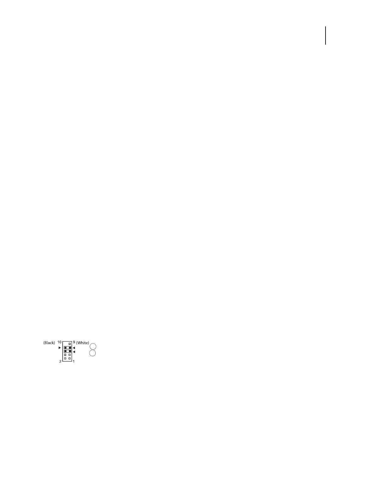
3 Connect the SW/LED cables from the Fiery QuickTouch panel to the J352 connector.
Figure 31: J352 connector on the printer interface board
4 Reassemble the E-85 and verify its functionality (see page 83).
1 LED cable connection
2 SW cable connection
1
2
Align triangle on cable connector as shown.