46Installation and Service Guide: Color Controller E-85
Replacing parts
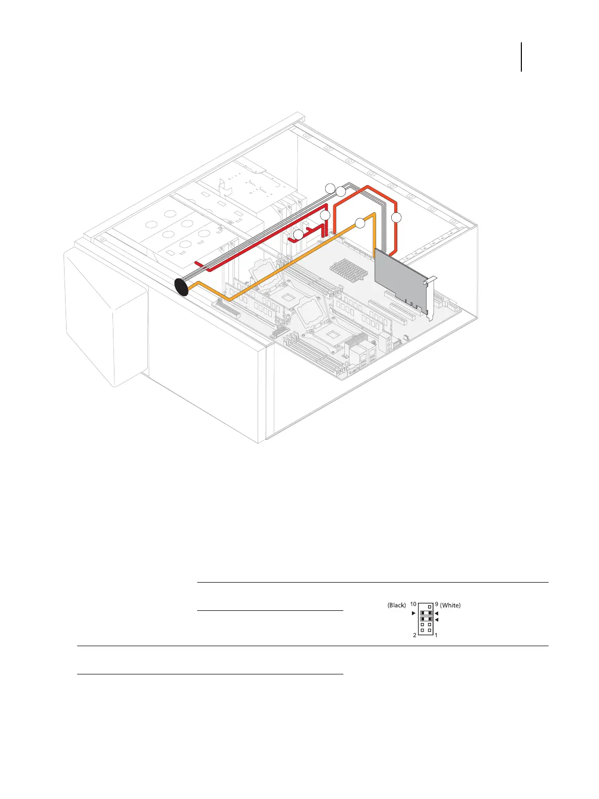
Figure 24: Data cable connections in the E-85
Cable key From To (on motherboard)
1 Fiery QuickTouch USB cable Fiery QuickTouch USB3_2
2 SATA data cable DVD drive
• Connector labeled 01
Mini SAS Connector (SATA0) - Connector labeled 01
3 SATA data cables HDD1, HDD2, and HDD3
• HDD1 - Connector labeled 02
• HDD2 - Connector labeled 03
• HDD3 - Connector labeled 04
Mini SAS Connector (SATA1-3)
4 Power switch connector (pin 5, 6) on the printer
interface board
Align triangle on cable connector as shown.
5 LED cable connector (pin 7, 8) on the printer
interface board
6 10-pin power button cable connector on the printer interface
board
FPIO_1
Note: For detailed locations of the connectors on the motherboard, see page 58.