45Installation and Service Guide: Color Controller E-85
Replacing parts
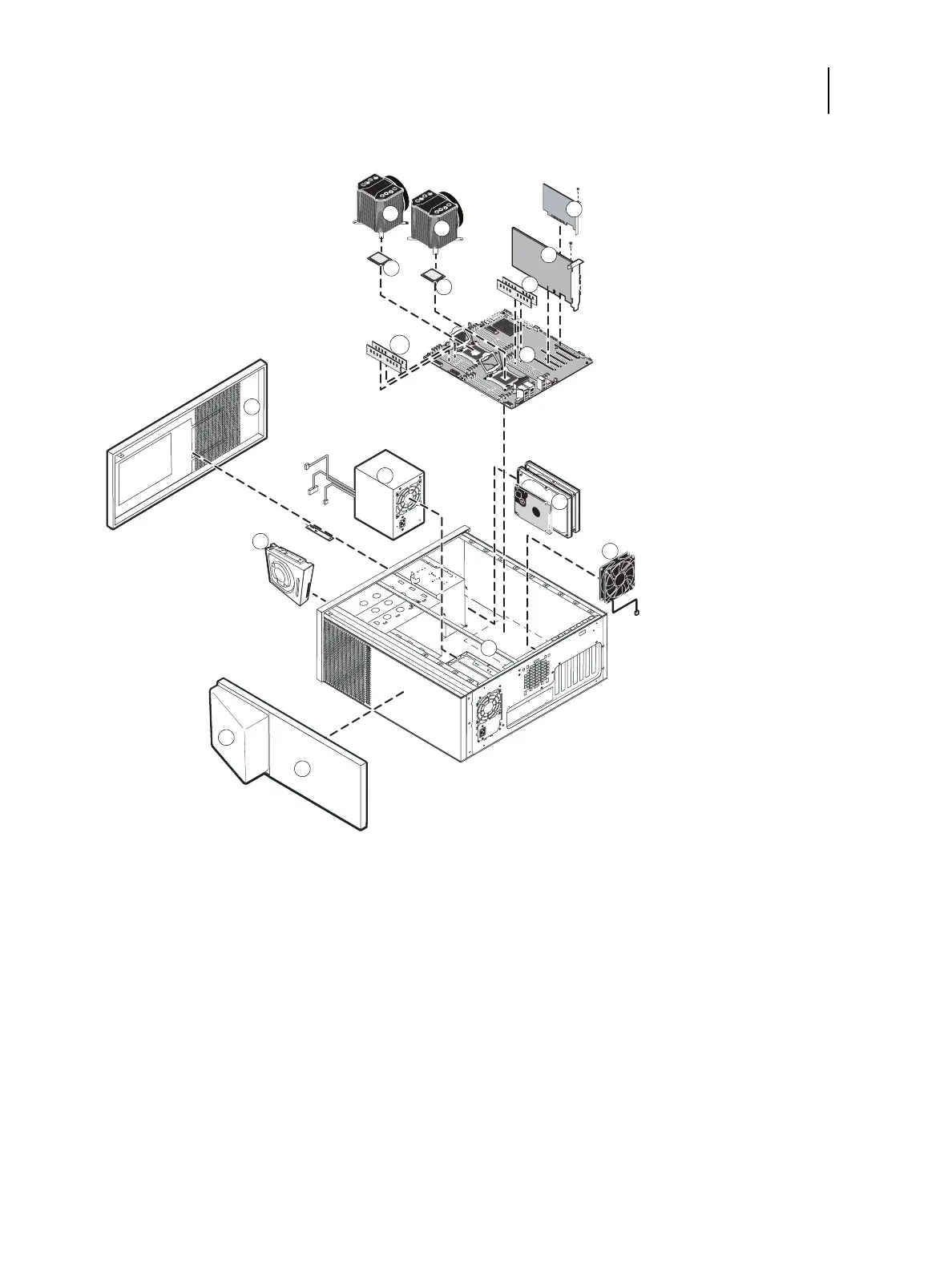
Figure 23: Exploded view of the E-85
1 Top chassis cover 8 Back fan
2 Fiery QuickTouch display panel 9 Motherboard
3 Chassis 10 DIMMs
4 DVD drive 11 Printer interface board
5 Front chassis cover 12 Graphics board
6 Power supply and power cables 13 CPUs cooling assemblies
7 HDDs (hard disk drives) 14 CPUs
Note: Monitor, mouse, keyboard, furniture, and other accessories are not shown.
1
10
2
4
5
6
7
8
9
10
11
12
13
14
3
13
14