47Installation and Service Guide: Color Controller E-85
Replacing parts
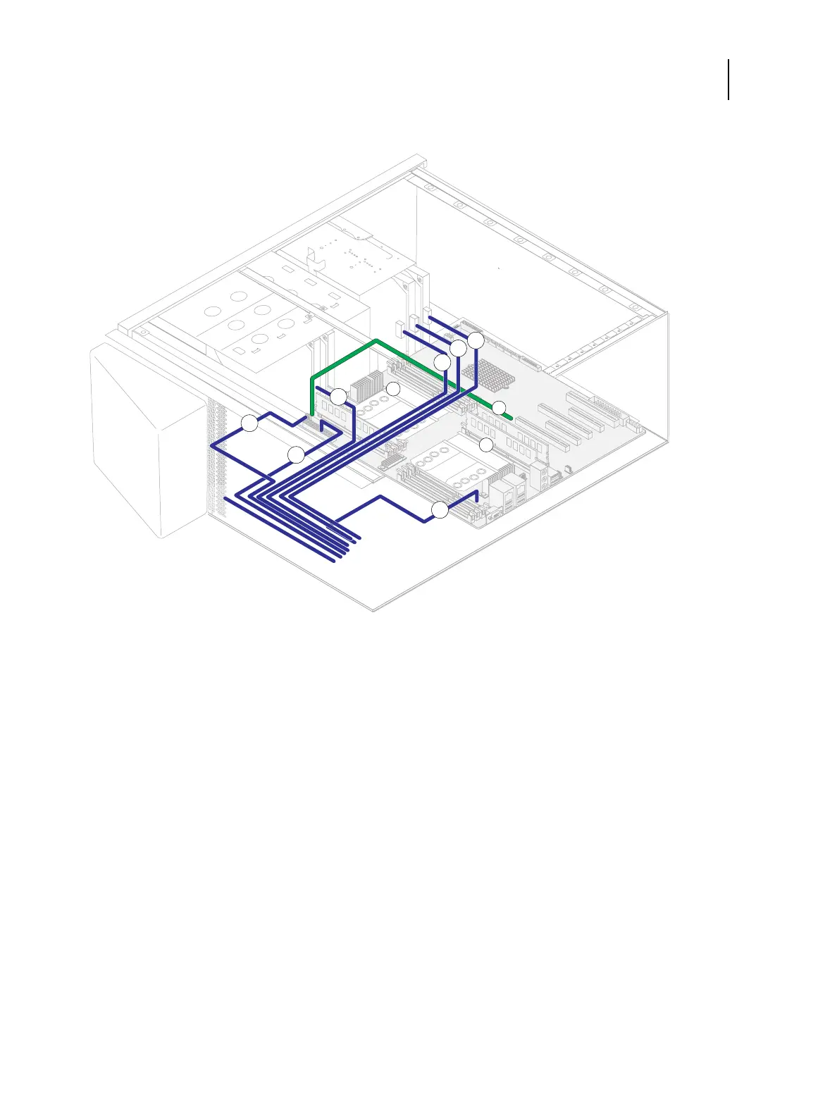
Figure 25: Power cable connections in the E-85
Cable key From To (on motherboard)
1 Back fan cable Back fan SYS_FAN1 (3-pin connector)
2 CPU0 fan cable CPU0 fan CPU0_FAN
3 CPU1 fan cable CPU1 fan CPU1_FAN
4 Power supply cables Power supply (not shown) a. PW3 (8-pin connector)
b. PW1 (24-pin connector)
c. PW2 (8-pin connector)
d. Molex power connector—DVD drive data/power cable
e. SATA power connector—HDD1
f. SATA power connector—HDD2
g. SATA power connector—HDD3
Note: For detailed locations of the connectors on the motherboard, see page 58.