Bluetooth Analyzers
Page 250 of 264 | Flying Leads Probe – Explorer
24. Flying Leads Probe – Explorer
The Flying Leads Cable connects the IO Probe Connector receptacle (located on the back panel) to one or more
external HCI, WCI-2, Audio I2S, generic communications (UART, SPI, SWD, and I2C), or logic signal
implementations. This traffic will be captured concurrently with through-the-air traffic and will be displayed in
the respective Overviews and other views as applicable (e.g., the
Instant Timing
View).
The user defines which pins will be used. This is done in Recording Options | Wired.
The IO Probe receptacle on the analyzer contains 26 pins (two rows of 13 pins), which mate with sockets on
the mating connector of the Flying Leads Cable.
The Logic Probe is keyed for proper orientation to the Analyzer’s IO Probe receptacle (sometimes referred to as
the Logic Connection) on one end and has socketed connections on each wire on the other end.
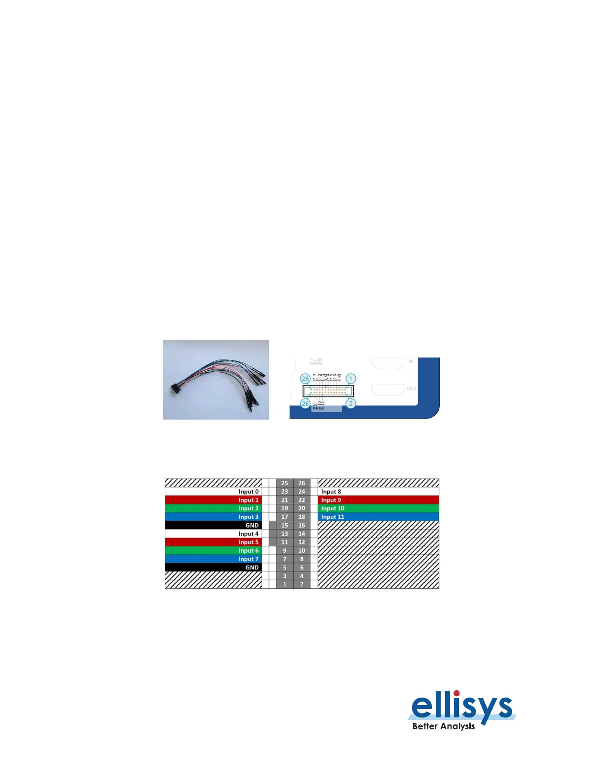
The figures below illustrate the keyed female plug on the probe, the keyed receptacle on the analyzer, and the
wire colors. N.C. = Not Connected.
Figure 15 Flying Leads Probe and IO Probe Receptacle
Figure 16 Probe Pin and Color Assignments - Explorer
 Loading...