Analyzer User Manual
Analyzer Hardware Overviews | Page 25 of 264
3.2 Front Panel Overview – Vanguard
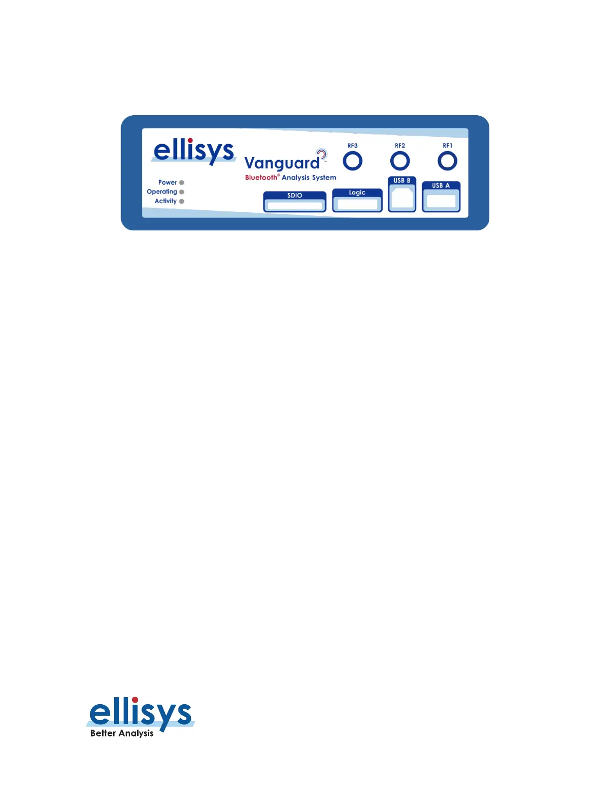
The front panel of the Vanguard is shown below:
Figure 4 Vanguard Front Panel
RF1 Connector
The (Standard SMA) RF1 connector is used to connect the antenna (supplied) for capture of BR/EDR, BLE, and
Wi-Fi.
RF2 Connector
The (Standard SMA) RF2 connector is used to connect the antenna (supplied) for capture of Wi-Fi and is also
shared for BR/EDR and BLE (see
Section 7.3, Bluetooth Capture Diversity
).
RF3 Connector
The (Standard SMA) RF3 connector is used to connect the antenna (supplied) for capture of Wi-Fi and WPAN.
USB B and USB A Connectors
The USB B and USB A connectors (USB 2.0 Standard-A and Standard-B) are used for USB HCI traffic capture.
Logic Connector
The Logic connector is used to attach to a flying-leads probe (supplied) for capture of logic signals, HCI (UART
and SPI), I2S Audio, and generic communications (I2C, SWD, UART, and SPI). See
Section
25, Flying Leads
Probe – Tracker and Vanguard
for details.
SDIO Slot
Not presently enabled for end-user access – factory programming access only.
 Loading...