Analyzer User Manual
Analyzer Hardware Overviews | Page 31 of 264
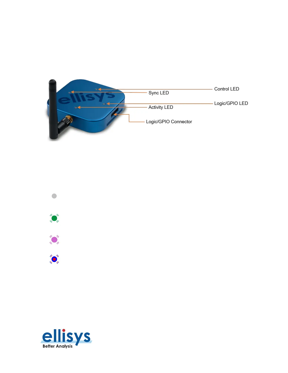
3.5 Connections and LEDs Overview – Tracker
The LED indicators and various connections on the Bluetooth Tracker are described below. There are four
multi-color LEDs on top of the unit, and on the sides, an antenna SMA receptacle, two Sync micro-USB
receptacles (not used), a Logic/GPIO connector, and for power and control, a micro-USB with an adjacent DC
jack (needed only when power supplied over the micro-USB connection is insufficient).
Figure 7 Tracker LEDs and Logic/GPIO Connector
Activity LED
The Activity LED, located next to the antenna, indicates whether wireless traffic is being detected. This LED will
be off until a recording is started.
Off: No wireless traffic detected / unit has not been initialized with a recording.
Green blinking: BLE traffic detected.
blinking: Wi-Fi traffic detected.
Green/Violet Blinking: BLE and W
i-Fi traffic detected.
 Loading...