110
ADVANCED USER GUIDE
Commander SX
IP66/Nema 4X variable speed drive
MENU 12: THRESHOLD DETECTORS, VARIABLE SELECTORS AND BRAKE CONTROL FUNCTION
CONTROL TECHNIQUES
3854 en - 03.2008 / b
: Function 1 variable 2 source
: Function 2 variable 2 source
Adjustment range :0.00 to 21.51
Factory setting :0.00
These parameters define the source parameter for variable 2
to be processed.
Any "numerical" parameter (read-only) can be assigned.
If an unsuitable parameter is selected, the value of the
variable will be 0.
: Function block 1 select
: Function block 2 select
Adjustment range :0 to 9
Factory setting :0
These parameters are used to define the function of the
internal variables processing block.
• If 12.10 or 12.30 equals 2, 3, 4 or 5:
When the result of the calculation is greater than 32767, the
output 12.11 or 12.31 is limited to 32767.
When the result of the calculation is less than -32768, the
output 12.11 or 12.31 is limited to -32768.
• If 12.10 or 12.30 equals 5:
To avoid a calculation error if V2 = 0, the result of the
operation will be 0.
• If 12.10 or 12.30 equals 7:
The ramp time defined by 12.15 or 12.35 corresponds to the
time for changing from 0 to 100% of the maximum value of the
source parameter.
• If 12.10 or 12.30 equals 9:
To avoid a calculation error, it is the absolute value of the
signal V1 which is taken into account before calculating its
square root or cube root.
: Function 1 output destination
: Function 2 output destination
Adjustment range :0.00 to 21.51
Factory setting :0.00
These parameters are used to select the destination of the
processed variable.
Any unprotected "non-bit" parameter can be assigned.
If an unsuitable parameter is selected, the value of the
variable taken into account is zero.
: Function block 1 output
: Function block 2 output
Adjustment range :± 100.00%
Indicates the value of the function output as a percentage of
the adjustment range for the destination parameter.
Note: When 12.11 or 12.31 is assigned to 0.00, the
adjustment range for 12.12 or 12.32 is ± 32000.
: Function 1 variable 1 scale
: Function 2 variable 1 scale
Adjustment range :± 4.000
Factory setting :1.000
Used to scale variable 1 before processing.
WARNING:
The value at the scaling output can only be between -
32767 and +32767. Take this into account according to
the adjustment range of the source parameter.
: Function 1 variable 2 scale
: Function 2 variable 2 scale
Adjustment range :± 4.000
Factory setting :1.000
Used to scale variable 2 before processing.
WARNING:
The value at the scaling output can only be between -
32767 and +32767. Take this into account according to
the adjustment range of the source parameter.
: Function 1 associated parameter
: Function 2 associated parameter
Adjustment range :0 to 100.00
Factory setting :0
Depending on its function, the internal variables processing
block may need an associated parameter.
If the block is used to implement a first-order filter, the
associated parameter is used as a coefficient; if it is used to
generate a ramp, this parameter is used to adjust the value of
the ramp (in seconds). The ramp time corresponds to the time
for changing from 0 to 100% of the maximum value of the
source parameter.
If the block is used as power, this parameter is used as
follows:
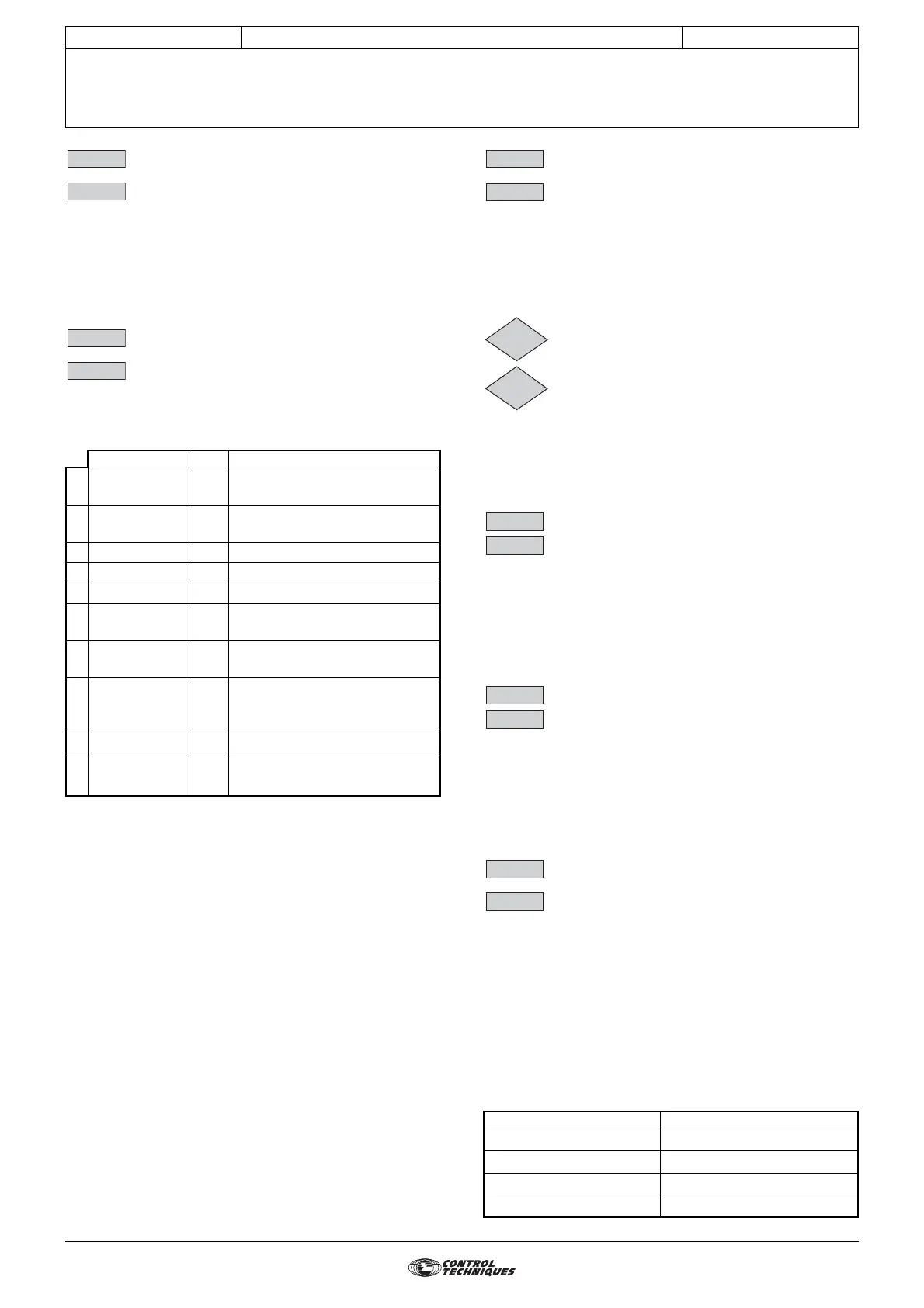
LCD LED Comment
0O=V1 In1
Used to transfer an internal
variable
1O=V2 In2
Used to transfer an internal
variable
2 O=V1+V2 IP2 Addition of 2 variables
3 O=V1-V2 I-2 Subtraction of 2 variables
4 O=V1xV2/100 IM2 Multiplication of 2 variables
5 O=V1/V2x100 Id2
Division of 2 variables:
O=(V1x100)/V2
6 O=filter/V1 Filt
Creation of a first-order filter:
O=V1/(12.x5 +1)
7O= ramp/V1raMP
Creation of a linear ramp. 12.x5
is used to adjust the value of the
ramp
8 O=abs(V1) abso Absolute value
9
O=V1^(12.x5) Puur
V1 to the power 12.x5 :
O=V1
12.x5
12.09
12.29
12.10
12.30
Function Associated parameter value
V1
2
2.00
V1
3
3.00
√V1 12.00
3
√V1
13.00
12.11
12.31
12.12
12.32
12.13
12.33
12.14
12.34
12.15
12.35