13
ADVANCED USER GUIDE
Commander SX
IP66/Nema 4X variable speed drive
MENU 0 CORRESPONDENCE AND AUTOMATIC PARAMETER SETTING
CONTROL TECHNIQUES
3854 en - 03.2008 / b
2 - MENU 0 CORRESPONDENCE
AND AUTOMATIC PARAMETER
SETTING
This section describes the interactions between menu 0 (user
menu) and the advanced menus (menus 1 to 21).
On the one hand, each parameter in menu 0 (01 to 80) is in
fact the image (address) of a parameter in the advanced
menus (e.g. parameter 02 corresponds to parameter 1.06 in
menu 1).
On the other hand, when a preset configuration is selected by
parameter 05, the drive automatically assigns parameters 11
to 24 of menu 0 to adapt the drive to the application, and also
then internally sets a list of parameters (different depending
on the selected preset configuration).
It is therefore useful to know these internal settings in cases
where the user starts parameter setting via menu 0, and ends
with the advanced menus.
Refer to the installation and commissioning manual ref. 3840
for commissioning using menu 0.
WARNING:
The purpose of the preset configurations in menu 0 is to
adapt the drive to the application as closely as possible.
However, if the user changes the structure of the
selected preset configuration by adding settings via the
advanced menus, the 05 parameter changes to "OPEn"
(unrestricted parameter setting).
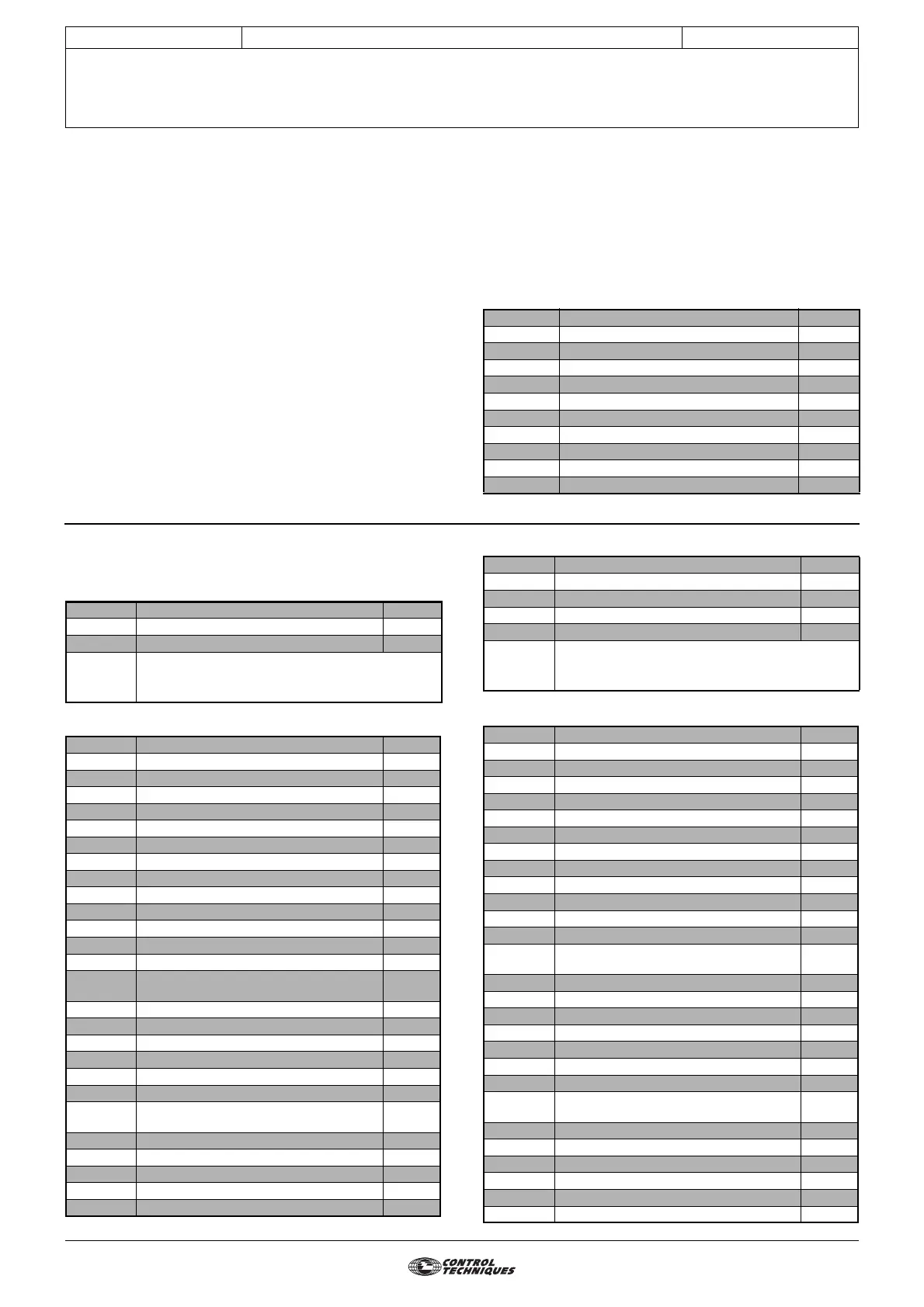
2.1 - Parameters 01 to 10
Parameter Name Address
01
Minimum reference clamp
1.07
02 Maximum reference clamp 1.06
03 Acceleration rate 2.11
04 Deceleration rate 2.21
05 Preset configuration select 11.46
06 Motor rated current 5.07
07 Motor rated speed 5.08
08 Motor rated voltage 5.09
09 Rated power factor (cos ϕ) 5.10
10 Quick setup menu access 11.44
2.2 - Parameters 11 to 24: preset
configurations
2.2.1 - Configuration 0: 05 = A1.A2
• Internal setting
2.2.2 - Configuration 1: 05 = A1.Pr
• Internal setting
Parameter Name Address
11 ADI1 mode 7.06
12 ADI2 mode 7.11
13
Not used
to
24
Parameter Name Value
1.14 Reference selector 0
6.04 Start/stop logic select 0
7.06 ADI1 mode 6
7.08 ADI1 input scaling 1 0 0
7.09 ADI1 input invert 0
7.10 ADI1 input destination 1.36
7.11 ADI2 mode 4
7.12 ADI2 input scaling 1 0 0
7.13 ADI2 input invert 0
7.14 ADI2 input destination 1.37
7.15 ADIO3 mode 1 0
7.16 ADIO3 scaling 1 0 0
7.17 ADIO3 input invert 0
7.18 ADIO3 input destination/output source 5.04
8.10 Secure disable select 1
8.11 DIO1 input or output invert 0
8.12 DI2 input invert 0
8.13 DI3 input invert 0
8.14 DI4 input invert 0
8.17 Output relay invert 0
8.21 DIO1 input destination/output source 10.03
8.22 DI2 input destination 6.30
8.23 DI3 input destination 6.32
8.24 DI4 input destination 1.41
8.27 Output relay source 10.01
8.31 DIO1 input or output select 1
Parameter Name Address
11 ADI1 mode 7.06
12 Preset reference 2 1.22
13 Preset reference 3 1.23
14 Preset reference 4 1.24
15
Not used
to
24
Parameter Name Value
1.14 Reference selector 1
1.15 Preset selector 0
6.04 Start/stop logic select 0
6.43 Run/Stop source 0
7.06 ADI1 mode 6
7.09 ADI1 input invert 0
7.10 ADI1 input destination 1.36
7.11 ADI2 mode 7
7.13 ADI2 input invert 0
7.14 ADI2 input destination 1.46
7.15 ADIO3 mode 1 0
7.17 ADIO3 input invert 0
7.18 ADIO3 input destination/output source 5.04
7.33 AIO3 feature 0
8.10 Secure disable select 1
8.11 DIO1 input or output invert 0
8.12 DI2 input invert 0
8.13 DI3 input invert 0
8.14 DI4 input invert 0
8.17 Output relay invert 0
8.21 DIO1 input destination/output source 10.03
8.22 DI2 input destination 6.30
8.23 DI3 input destination 6.32
8.24 DI4 input destination 1.45
8.27 Output relay source 10.01
8.31 DIO1 input or output select 1
8.41 DIO1 feature 0