15
ADVANCED USER GUIDE
Commander SX
IP66/Nema 4X variable speed drive
MENU 0 CORRESPONDENCE AND AUTOMATIC PARAMETER SETTING
CONTROL TECHNIQUES
3854 en - 03.2008 / b
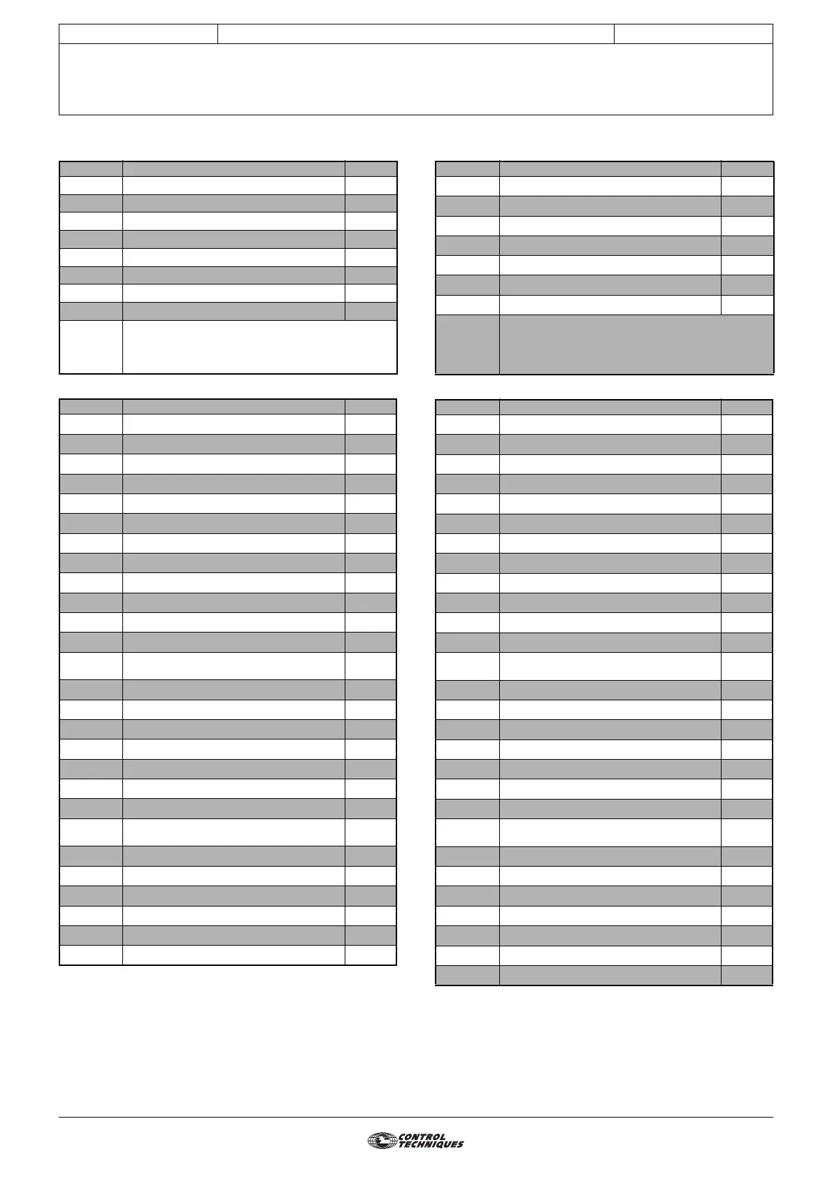
2.2.5 - Configuration 4: 05 = 8Pr
• Internal setting
2.2.6 - Configuration 5: 05 = E.Pot
• Internal setting
Parameter Name Address
11
Preset reference 1
1.21
12 Preset reference 2 1.22
13 Preset reference 3 1.23
14 Preset reference 4 1.24
15 Preset reference 5 1.25
16 Preset reference 6 1.26
17 Preset reference 7 1.27
18 Preset reference 8 1.28
19
Not used
to
24
Parameter Name Value
1.14 Reference selector 3
1.15 Preset selector 0
6.04 Start/stop logic select 0
6.43 Run/Stop source 0
7.06 ADI1 mode 7
7.09 ADI1 input invert 0
7.10 ADI1 input destination 1.46
7.11 ADI2 mode 7
7.13 ADI2 input invert 0
7.14 ADI2 input destination 1.47
7.15 ADIO3 mode 1 0
7.17 ADIO3 input invert 0
7.18 ADIO3 input destination/output source 5.04
7.33 ADIO3 feature 0
8.10 Secure disable select 1
8.11 DIO1 input or output invert 0
8.12 DI2 input invert 0
8.13 DI3 input invert 0
8.14 DI4 input invert 0
8.17 Output relay invert 0
8.21 DIO1 input destination/output source 10.03
8.22 DI2 input destination 6.30
8.23 DI3 input destination 6.32
8.24 DI4 input destination 1.45
8.27 Output relay source 10.01
8.31 DIO1 input or output select 1
8.41 DIO1 feature 0
Parameter Name Address
11
ADI1 mode
7.06
12
Manual motorised pot reset
9.28
13
Automatic motorised pot reset
9.21
14
Motorised pot bipolar select
9.22
15
Motorised pot rate
9.23
16
Motorised pot scale factor
9.24
17
Motorised pot reference
9.03
18
Not usedto
24
Parameter Name Value
1.09 R e f e r e n c e o f f s e t v a l i d a t i o n 1
1.14 Reference selector 1
6.04 S t a r t / s t o p l o g i c s e l e c t 0
6.43 Run/Stop source 0
7.06 A D I 1 m o d e 6
7.09 ADI1 input invert 0
7.10 ADI1 input destination 1.36
7.11 ADI2 mode 7
7.13 A D I 2 i n p u t i n v e r t 0
7.14 ADI2 input destination 9.26
7.15 A D I O 3 m o d e 1 0
7.17 ADIO3 input invert 0
7.18 ADIO3 input destination/output source 5.04
7.33 ADIO3 feature 0
8.10 S e c u r e d i s a b l e s e l e c t 1
8.11 DIO1 input or output invert 0
8.12 D I 2 i n p u t i n v e r t 0
8.13 DI3 input invert 0
8.14 D I 4 i n p u t i n v e r t 0
8.17 Output relay invert 0
8.21 DIO1 input destination/output source 10.03
8.22 DI2 input destination 6.30
8.23 DI3 input destination 6.32
8.24 DI4 input destination 9.27
8.27 Output relay source 10.01
8.31
DIO1 input or output select 1
8.41
D I O 1 f e a t u r e 0
9.25
Motorised pot destination 1.04